CIP 1500 – User and Maintenance Manual
9
Chapter 3
TECHNICAL DESCRIPTION OF THE MACHINE
The chipper Mod.
CIP 1500
has been designed and manufactured to reduce
large volumes of branches, sawmill waste and pruning remainders into small-
sized pieces.
The material, entered to the inlet port, is drawn by two feeding rollers against
the chipper disk.
The two draw rollers are driven by independent hydraulic motors with adjustable
speed.
The chipper disk, rotating at 1500 r.p.m., is fitted with 2 blades, cutting the
material into fragments, 5 to 20 mm long, and one counter-blade, secured to the
structure, further reducing them into chips.
The chips are ejected by the centrifugal action of the chipper disk into an outlet
conveyor.
Such conveyor may be oriented according to the outlet direction.
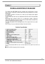
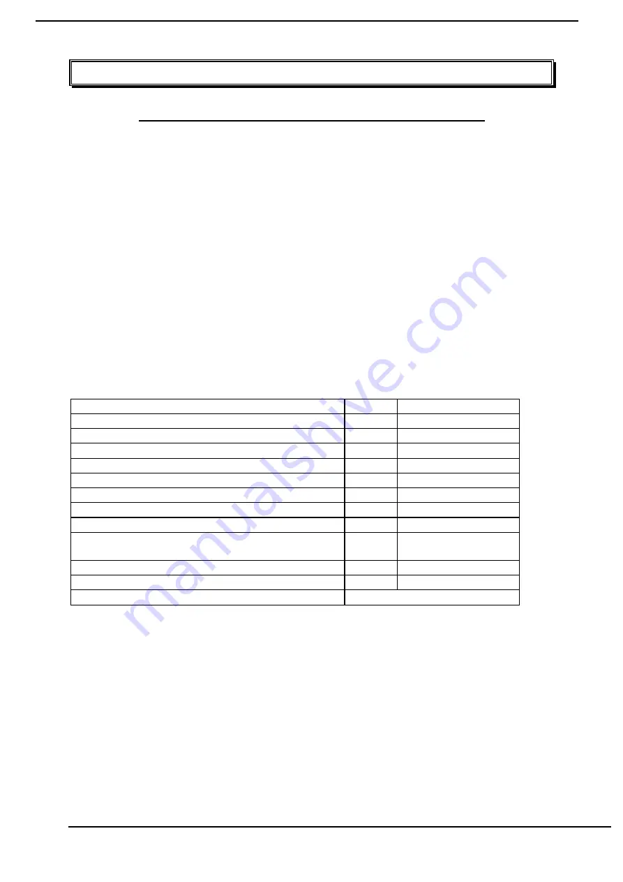
Technical Specification
•
Outlet month dimensions
mm
840 x 610
•
MAX chipping diameter
mm 150
•
Flywheel diameter
mm 680
•
Flywheel thickness
mm 30
•
Blades
n°
2 ÷ 3
•
Flywheel speed of rotation (max)
r.p.m. 1500
•
Chips length
mm
6 ÷ 12
•
Diameter of feeding rollers
mm 165-155
•
Max. distance between feeding rollers
mm 180
•
Stand-alone engine power rating
(LOMBARDINI / HONDA / ELECTRIC 22 kW)
kW
17.7 / 19.8 / 22 / 27.2
•
Hourly output
m
3
8 ÷ 10
•
Airborne noise produced by the machine
( 1 )
Db (A)
?
•
Weight
See data plate
( 1 ) The above-mentioned MAX noise level has been measured in the operator area, while he was
working.
?
Higher than 85 dB: wearing ear protectors is compulsory.


