background image


www.GreenSeriesFitness.com


©June 2015 


Call Toll free at 800-269-7130 

VOR-IC6000-G      Revision 1.1 

10 

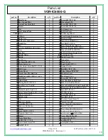
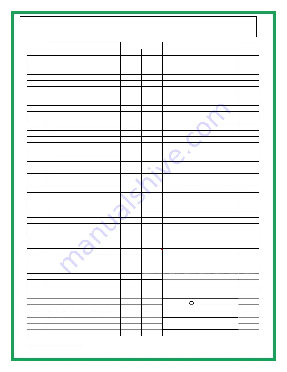
Parts List 

  VOR-IC6000-G   


part no.

description

q'ty

part no.

description

q'ty

1

Main Frame

1

47

Screw M5*P0.8*6L

2

2

Rear Ground Tube

1

48

Sleeve8mm*15L

1

3

Groung Tube Fixed Bolt

4

49

Screw M5*P0.8*15L

8

4

Washer

4

50

Screw M8*P1.25*8L

1

5

Nut

4

51

Left Inner Cover

1

6

Front Ground Tube

1

52

Left Out Cover

1

7 R/L

Pedal

1

53

PU Moving Wheel 

2

8

V Block

2

54

Front Ground Tubes End Cap

2

9

Bottle Cage

2

55

Bearing 608ZZ

4

10

Bottle cages fixed screw

4

56

Nut 8*30L W/M6*P1.0

2

11

Handle Bar

1

57

Nut M6*P1.0*12L

2

12

Belt

1

58

Rear Ground Tubes End Cap

2

13

scres for handlebar and seat post

2

59

BB Axles Bearing SKF 6004ZZ

2

14

Stem

1

60

Sleeve 24OD*20.1ID*27L

1

15

Seat Post

1

61

B.B Axle 25mm*20mm*128L

1

16

Saddles Slider

1

 62L

Left Crank 175L

1

17

Saddle

1

 62R

Right Crank 175L

1

18

Lock Lever

4

63

Flange Nut

2

19

Set Screw M6*P1.0*8L

2

64

Dusty Cover

2

20

Plastic Seal cover

2

65

Lock Nut M20*P1.0

1

21

Axles Adjust ScrewM6*P1.0*95L

2

66

Spring Washer

4

22

POP Cover

2

67

Bolt M10*P1.5*15L

4

23

Plastic Sleeve

4

68

Pulley 265mm*5PK*21T

1

24

Stem & Seat Post End Cap

4

69

Right Out Cover

1

25

Handlebar/ saddle slider set screw 

2

70

Right Inner Cover

1

26

Safety Bolt 

2

71

Screw M5*P0.8*10L

2

27

Adjust Knob

1

72

Out Alloy Ring of Fly Wheel 

1

28

Moving Part 20 OD*34L

1

73

Inner Cast Iron Fly Wheel 

1

29

Lock Nut 3/8" *16t*6T

1

74

Sleeve For BB Axle 22mm*18mm*56L

1

30

Nut

2

75

Bearing for Fly Wheel SKF 6203ZZ

2

31

Washer18mm*8.5mm*1.5t

2

76

Nut M17*P1.0*8t

2

32

Spring 18mm*2mmD*65L* 9 Coils

1

77

Fly Wheels Axle

1

33

Stud 12.7mm*160L

1

78

Screw M5*P0.8*6L

5

34

Saddle clamp 

1

79

Nut M12*P1.25

2

35

Nut

1

80

Washer 27mm*13mm*3t

2

36

Brake set adjuster

1

81

Nut3/8"*16t*6T

2

37

screw M6*P1.0*8L

1

82

Rear Ground Stablize Adjuster

2

38

Brake set Fix Bracket

1

81

Nut3/8"*16t*6T

2

39

Washer

2

82

Rear Ground Stablize Adjuster

2

40

Screw M6*P1.0*15L

2

83

washerφ16×φ8.5×1.5t

2

41

Magnetic Side Cover

2

84

plastic cone on handlebar slider

2

42

Magnet

6

85

screw M8×P1.25×15L

1

43

Plastic Brake Bass 

1

86

washer

φ

16×

φ

5×1.5t

1

44

Bolt M8*P1.25*20L

1

87

nut M8×P1.25

1

45

Sleeve 8mm*11mm*12L

1

88

 steel plate 

φ

20×3t

1

46

Nut M8*P1.25

1


Summary of Contents for VOR-IC6000-G

Page 1: ...Fitness com June 2015 Call Toll free at 800 269 7130 VOR IC6000 G Revision 1 1 Owner s Manual VOR IC6000 G Light Commercial Indoor Cycle Install Date _________________________ Serial Number __________...

Page 2: ...Revision 1 1 1 2BTABLE OF CONTENTS SAFETY PRECAUTIONS 2 3 Important information how often you exercise how hard you exercise how long you exercise target heart rate zone TECHNICAL SPECIFICATIONS 4 ASS...

Page 3: ...own to decrease the potential for injury Do not dismount the bike until both the pedals and flywheel have come to a complete stop Do not attempt to use this bike at high speeds or in standing position...

Page 4: ...ong you exercise Sustained exercise conditions your heart lungs and muscles The longer you are able to sustain exercise within your target heart range the greater the aerobic benefits To begin maintai...

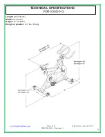
Page 5: ...eenSeriesFitness com June 2015 Call Toll free at 800 269 7130 VOR IC6000 G Revision 1 1 4 TECHNICAL SPECIFICATIONS VOR IC6000 G Length 43 109 cm Width 24 61cm Height 47 119cm Weight of product 127 lbs...

Page 6: ...www GreenSeriesFitness com June 2015 Call Toll free at 800 269 7130 VOR IC6000 G Revision 1 1 5 UNPACKING ASSEMBLY VOR IC6000 G...

Page 7: ...n the bolts Step 3 Pedals 1 Attach the pedals 70R 70L into the crank arms 62R 62L Each pedal is marked with the letter R right or L left to denote the side of the bike they are to be installed NOTE Th...

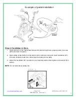
Page 8: ...s height at a proper position then use 18 lock lever to tighten 2 Open safety screw 26 from the stem s 14 extension tube and insert handlebar 11 into stem extension tube then screw back the safety scr...

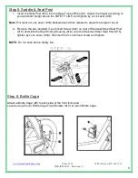
Page 9: ...er of Lock Lever 18 backward and then release to adjust the angle of Lever 2 Remove the pre installed V Lock fixed Screw 20 on rear of Stainless Steel Seat Post 15 and slide the Seat Sliding Housing 1...

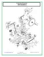
Page 10: ...www GreenSeriesFitness com June 2015 Call Toll free at 800 269 7130 VOR IC6000 G Revision 1 1 9 Exploded Diagram VOR IC6000 G...

Page 11: ...es Adjust ScrewM6 P1 0 95L 2 66 Spring Washer 4 22 POP Cover 2 67 Bolt M10 P1 5 15L 4 23 Plastic Sleeve 4 68 Pulley 265mm 5PK 21T 1 24 Stem Seat Post End Cap 4 69 Right Out Cover 1 25 Handlebar saddle...

Page 12: ...or backwards Undo the Quick Release lever located below the slider Slide the handlebar stem assembly forwards or backwards until you reach the right position Then securely re tighten the Quick Releas...

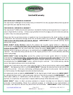
Page 13: ...ansferable Excluding Indoor Cycling Bikes GREEN SERIES Indoor Cycling Bikes warrant this product and its parts against defects in materials or workmanship for five 5 years frame two 2 years parts one...

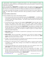
Page 14: ...on ii disasters such as fire flood lightning or improper electric current or iii service or alteration by anyone other than an authorized GREEN SERIES representative iv damages incurred through irresp...

Page 15: ...der the following conditions fees 1 GREEN SERIES will refund the cost of equipment only Customer is responsible for shipping and handling fees incurred to and from the product s return 2 No refund wil...

Page 16: ...any product or parts installed by other manufacturers Technical support should be pursued through channels offered by the equipment s individual technician support GREEN SERIES accepts no liability f...

Reviews: