background image

1

Grease Grabber™ Power Play Kitchen Exhaust Pollution Control System

Installation, Operation and Maintenance Manual

Please read and save these instructions. Read carefully before attempting to assemble, install, operate or maintain the 
product described. Protect yourself and others by observing all safety information. Failure to comply with instructions 
could result in personal injury and/or property damage! Retain instructions for future reference.

®

Part Number 474754 

Grease Grabber™ Power Play

Kitchen Exhaust Pollution Control System

Grease Grabber™ Power Play

The Greenheck Grease Grabber™ Power Play 
is a pre-engineered electrostatic precipitator 
type filtration pollution control unit with 
integral exhaust fan (available without exhaust 
fan as an option). The unit is designed to 
remove grease and smoke particles as well 
as odor molecules from the kitchen exhaust 
airstream. This installation manual covers 
procedures for receiving, installing, and 
maintaining the filtered section of the unit.
For additional instructions and maintenance 
information on the integral exhaust fan, 
when applicable, refer to the fan nameplate 
to determine model type and visit www.greenheck.com to 
download the corresponding manual.

Only qualified personnel should install this system. 
Personnel should have a clear understanding of these 
instructions and should be aware of general safety 
precautions. Improper installation can result in electric 
shock, possible injury due to coming in contact with 
moving parts, as well as other potential hazards. 
Other considerations may be required if high winds 
or seismic activity are present. If more information 
is needed, contact a licensed professional engineer 
before moving forward.

• 

Follow all local electrical and safety codes, as well 
as the National Electrical Code (NEC), the National 
Fire Protection Agency (NFPA), where applicable. 
Follow the Canadian Electric Code (CEC) in 
Canada.

• 

The rotation of the fan wheel is critical. It must 
be free to rotate without striking or rubbing any 
stationary objects.

• 

Fan motor must be securely and adequately 
grounded.

• 

Do not spin fan wheel faster than maximum 
cataloged fan rpm.  Adjustments to fan speed 
significantly effects motor load. If the fan RPM is 
changed, the motor current should be checked to 
make sure it is not exceeding the motor nameplate 
amps.

• 

Do not allow the power cable to kink or come in 
contact with oil, grease, hot surfaces or chemicals. 
Replace cord immediately if damaged.

• 

Verify that the power source is compatible with the 
equipment.

• 

Never open access doors to a duct while the fan is 
running.

• 

The precipitator contains safety electrical interlock 
switches at all maintenance access doors. Do not 
attempt to defeat these interlocks.

General Safety Information

DANGER

Always disconnect power before working on or near 
this equipment. Lock and tag the disconnect switch 
or breaker to prevent accidental power up.

CAUTION

When servicing the fan, motor may be hot enough 
to cause pain or injury. Allow motor to cool before 
servicing.

CAUTION

Do not install this equipment in explosive 
atmospheres.

Summary of Contents for 474754

Page 1: ...ck possible injury due to coming in contact with moving parts as well as other potential hazards Other considerations may be required if high winds or seismic activity are present If more information is needed contact a licensed professional engineer before moving forward Follow all local electrical and safety codes as well as the National Electrical Code NEC the National Fire Protection Agency NF...

Page 2: ...an dry atmosphere Remove any accumulations of dirt water ice or snow and wipe dry before moving to indoor storage To avoid sweating of metal parts allow cold parts to reach room temperature To dry parts and packages use a portable electric heater to get rid of any moisture build up Leave coverings loose to permit air circulation and to allow for periodic inspection OUTDOOR Units designed for outdo...

Page 3: ...rease and smoke particles as they pass These particles are then repelled by positively charged plates and collected on negatively charged plates Upon completion of each cooking day a wash sequence is initiated for the self cleaning function of the electrostatic cell via the remote mounted control panel The aluminum mesh mist eliminator prevents wash water from entering the safety filter and carbon...

Page 4: ...Field weight will vary depending upon final selections such as fan type accessories etc Approximate weights are shown in the table below 4 The unit can be positioned on a base or curb suitable for this purpose 5 The unit must be anchored to its base curb 6 Alternatively the unit may be suspended from an adequate overhead structure using suitable undercarriage or hanging rods by others If the unit ...

Page 5: ...tions shall have a liquid tight external weld An inlet transition is furnished to match the inlet duct size The inlet transition is furnished with a listed duct access door for inspection and cleaning Units intended for indoor mounting are provided with an outlet mounting flange either at the unit discharge or as part of a factory supplied UL 762 listed exhaust fan Outlet ductwork from the exhaust...

Page 6: ...d at the top and side of the system power pack and the sides of the terminal box on top of the cabinet assembly Use a knockout punch to open holes for minimum 1 2 inch conduit Use caution to keep the system power pack and terminal box interiors free of scraps and other debris Once conduit is in place and high voltage cable has been run terminate the high voltage cables at the power pack by strippi...

Page 7: ...er pack to terminals 1TB16 1TB18 1TB15 and 1TB19 respectively in the system control panel Connect the junction box on top of the system cabinet to the system control panel using 14 gauge wire Connect terminals 5TB1 and 5TB2 access door safety interlock to terminals 1TB4 and 1TB13 respectively in the system control panel Also connect terminals 5TB5 5TB7 upstream wash motor 5TB8 and 5TB10 downstream...

Page 8: ...top minute use numbered keypad to enter minutes press enter Enter all days of the week Sunday thru Saturday either on or off and start stop time System Wash Schedule Scroll down to wash start Scroll over to hour use numbered keypad to enter hour in military time press enter Scroll over to minute use numbered keypad to enter minutes press enter Scroll down to day of week Scroll over to off press en...

Page 9: ...the system This may be required if a WASH cycle is inadvertently initiated As indicated previously in FIGURE 6 there is a 5 minute delay period after the WASH button is pushed before the wash process begins If the WASH cycle is accidentally initiated the operator may reset the system during the 5 minute delay period and the system will return to NORMAL operation If the system is reset after the 5 ...

Page 10: ...be removed and thoroughly cleaned on a minimum two 2 week interval removing any grease and particulate buildup B Ionizing Collecting Cells The ionizing collecting cells should be inspected for grease build up on a monthly basis This monthly inspection should be done after the system has completed a wash cycle If grease build up is apparent remove cells and clean manually The cells should be remove...

Page 11: ...ly grasping the red boots and pulling them from the high voltage plugs 8 Carefully remove a cell from the cabinet Each 2 ft cell weighs approximately 65 lbs so use caution when handling Use care not to bend or dent the collecting plates or framework 9 Carefully inspect the cell for bent collector plates Bent plates may be carefully straightened by hand using needle nose pliers 10 Inspect the cell ...

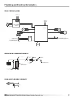
Page 12: ...TALLIC CONDUIT FIRE SYSTEM N C DRY CONTACT H V POWER SUPPLY SHUT DOWN THAT OPENS WHEN FIRE SYSTEM ACTIVATES ___ V __ HZ 1 PH __ AMP SERVICE INPUT POWER WATER COLUMN ESP DRAIN PAN 3 INCH DRAIN LINE 1 2 INCH DETERGENT DISPENSER LINE WASH MANIFOLDS SOLENOID VALVE BACKFLOW PREVENTER PRESSURE GAUGE 0 100 PSI 55 GALLON DETERGENT DISPENSER 140 F WATER SUPPLY LINE BY OTHERS Y STRAINER BALL VALVE VAC 3 PH ...

Page 13: ...4 4202 G X1 X2 F3 BY OTHERS EVENT OF A FIRE CLOSES IN THE DRY CONTACT FIRE SYSTEM N O 6 4 F F F F F F F F F1 F2 DENOTES TERMINAL CONNECTION IN POWER PLAY CONTROL PANEL DENOTES FIELD WIRING CONTROL PANEL BY OTHERS EVENT OF A FIRE CLOSES IN THE DRY CONTACT FIRE SYSTEM N O F F F ___V 60HZ 3PH INPUT POWER C FAN MOTOR ___ VAC 120 VAC OL 24 322CR2 23 CONTROL PANEL POWER PLAY OFF AUTO 4222 4221 1TB30 1TB...

Page 14: ...7 HIGH VOLTAGE CABLE SUPPLIED BY GREENHECK 50 BLUE 50 RED DETERGENT LEVEL SENSOR WASH MOTOR UP STREAM 120V 60HZ 1PH 1 20 HP 15 RPM 1 20 HP 15 RPM 120V 60HZ 1PH DOWN STREAM WASH MOTOR RUN IN SEPARATE CONDUIT 4201 322CR1 1TB27 6TB2 6TB1 3TB4 4TB4 6TB3 3TB15 2 2TB4 3 4 5 6 7 8 9 1TB16 1TB18 1TB15 1TB19 POWER PLAY SYSTEM CONTROL X1 X2 412PL 414M M 410M M 1TB23 1TB24 2TB21 1TB25 2TB20 2TB22 ESP JUNCTIO...

Page 15: ...SHOWN AND THE FIRE SUPPRESSION SYSTEM DISCHARGES 2 THE SUPPLY FAN WILL SHUT OFF FIRE SUPPRESSION WIRING NOTES SEE SHEET 2 SEE SHEET 2 X2 X1 2141 1121 1121 7TB14 7TB15 7TB9 7TB10 3161 1001 1121 2121 X1 3161 1121 1001 428PL G X2 2121 4 3 250PB 252PB 7TB2 7TB12 7TB11 7TB3 7TB4 7TB1 2141 1341 1321 1001 1001 7TB17 7TB16 7TB6 7TB5 7TB19 1121 3181 1001 2041 3201 X1 X1 1341 1321 X2 1001 3 4 426PL R 1001 4...

Page 16: ..._______ Date___________________ Time______________ AM PM Notes ___________________________________________ _________________________________________________ _________________________________________________ _________________________________________________ _________________________________________________ Date___________________ Time______________ AM PM Notes ______________________________________...

Reviews: