background image

9

Centrifugal Single-Width Blower

®

The intent of this procedure is to allow a field service 
technician to replace bearings with the fan remaining 
in place in its intended application. All work can 
be conducted by accessing the bearings by either 
removing a shaft guard, a weatherhood or working 
under a weatherhood (if applicable). This is dependent 
on the size of the unit. This procedure assumes the 
power source has been locked out prior to removing 
guards and covers, belts and pulleys have been 
loosened and removed properly and extended 
lubrication lines have been disconnected at the 
bearing. In some cases, it may be necessary to remove 
the fan inlet cone and wheel if the bearings cannot be 
removed due to corrosion or damage. 

Bearing Removal

This procedure assumes proper safety measures have 
been taken.
•  Read and follow all instructions carefully.
•  Disconnect and lockout power before installation 

and maintenance.

•  Driven sheaves and belts have already  

been removed.

• 

Arr. 3 fans (if applicable)

 will need the inlet ducting 

removed to access the non-drive bearing removal.

•  Shaft black coating can be removed with a solvent 

similar to a brake/carburetor cleaner.

  1.  Scribe a line around the shaft by both bearings 

and around the bearing base to the bearing 
support or write down the measurement from the 
end of the shaft to the bearings. This will help in 
repositioning the new bearing and wheel cone 
overlap.

  2.  Follow the bearing manufacturers’ procedures for 

removal and installation.

  3.  Before removing the bearing bolts, make sure the 

shaft is supported slightly. Remember to consider 
the wheel weight on the shaft. (Arr. 3 may need 
the wheel to be suspended through an access 
door on top of the fan.)

  4.  Remove both bearings from the shaft and clean/

remove any burrs using an emery cloth or file.

  5.  Clean mounting surface of any dirt or grease.

Bearing Installation

  1.  Before installing, read bearing manufacturers’ 

procedures. Before putting the new bearings on 
the shaft, you may need to break what is called 
swivel torque on the bearings (depending on style 
of bearing). This is done by holding the bearing 
housing securely and being able to move the inner 
bearing race around freely.

  2.  Apply light film of oil on shaft, then gently slide the 

new bearings onto the shaft.


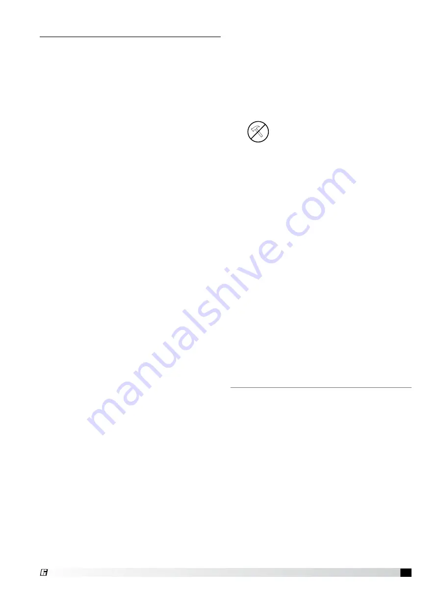
Do not hammer bearing onto shaft!

  3.  Align bearings on shaft with the previous scribe 

marks that are on the shaft and lock bearing to 
shaft.

  4.  Put bolts into mounting surface and bearings. Do 

not tighten.

  5.  Remove blocks if shaft is supported. (Arr. 3 

release the weight of the wheel onto the bearing).

  6.  Set bearings on support with the scribed marks 

locating the bearings. Make sure bearings are 
square and level with the shaft.

  7.  Tighten bolts and torque bearing bolts, bearing 

set screws/locking collars as per bearing 
manufacturers’ procedures.

  8.  Rotate shaft by hand to help allow the bearings to 

help set in. Also at this time, listen for any unusual 
noises such as wheel rubbing on cone and any 
bearing noise.

  9.  Connect extended lube lines in new bearings if 

needed.

 10.  Reinstall the drive sheaves and belts. Check the 

belt alignment.

 11.  Make sure to reinstall all guards and follow proper 

safety measures before starting up the fan.

Bearing Replacement

Motor maintenance is generally limited to cleaning 
and lubrication. Cleaning should be limited to exterior 
surfaces only. Removing dust and grease buildup on 
the motor housing assists proper motor cooling. Never 
wash-down motor with high pressure spray.
Greasing of motors is only intended when fittings are 
provided. Many motors are permanently lubricated for 
life and require no further lubrication. Motors supplied 
with grease fittings should be greased in accordance 
with the motor manufacturer’s recommendations.
Consult fan manufacturer for instructions on the 
removal of replacement motors.
It is recommended to select VFD compatible motors 
for CSB fans and connect the motors through a VFD 
controller to avoid sudden torque on the impeller, and 
the belts ensuring soft start and safe operation. 

Motors

Summary of Contents for CSB

Page 1: ...to rotate without striking or rubbing any stationary objects 3 Motor must be securely and adequately grounded 4 Do not spin fan wheel faster than the maximum cataloged fan RPM Adjustments to fan speed with Variable Frequency Drives VFD may affect motor load If the fan RPM is changed the motor current should be checked to make sure it is not exceeding the motor nameplate amps 5 Do not allow the pow...

Page 2: ...atures should be evenly maintained between 30 to 110 F 1 to 43 C wide temperature swings may cause condensation and sweating of metal parts All accessories must be stored indoors in a clean dry atmosphere Remove any accumulations of dirt water ice or snow and wipe dry before moving to indoor storage To avoid sweating of metal parts allow cold parts to reach room temperature To dry parts and packag...

Page 3: ... assure no parts are rubbing 3 Ensure wheel backplate is equidistant from inlet cone ID on both sides in case of double wide wheel for proper wheel centering Table of Contents System Set Up 4 Installation Discharge Positions 5 Method for Wheel Centering 5 V Belt Drive Installation 5 Alignment of Pulleys and Belts 5 Wheel Rotation 5 Unit Start Up Visual Inspection of Equipment 6 Check 6 Additional ...

Page 4: ... 6 0 4 R o t ati One fan wheel diameter 3 4 to one fan wheel diameter One fan diameter 3 4 to one fan wheel diameter Parallel Fan Installation System Set Up Installations with inlet or discharge configurations that deviate from this manual may result in reduced fan performance Restricted or unstable flow at the fan inlet can cause pre rotation of incoming air or uneven loading of the fan wheel yie...

Page 5: ...sheaves on shafts Do not drive sheaves on as this may result in bearing damage 3 Align fan and motor sheaves with a straight edge or string and tighten 4 Place belts over sheaves Do not pry or force belts as this could result in damage to the cords in the belts 5 Adjust the tension until the belts appear snug Run the unit for a few minutes and allow the belts to set properly 6 With the fan off and...

Page 6: ...ding on how it has been wired To reverse rotation of a 3 phase motor interchange any two of the three electrical leads Single phase motors can be reversed by changing internal connections as described on the motor label or wiring diagram 2 Fans with multi speed motors should be checked on low speed during initial start up 3 Check for unusual noise vibration or overheating of bearings Refer to the ...

Page 7: ...o loose or too tight or misaligned sheaves Abnormally high belt tension or drive misalignment will cause excessive bearing loads and may result in failure of the fan and or motor bearings Conversely loose belts will cause squealing on start up excessive belt flutter slippage and overheated sheaves Either excessively loose or tight belts may cause fan vibration When replacing V belts on multiple gr...

Page 8: ...ting and until clean grease is seen purging from the bearing The lubrication interval may be modified based on the condition of the purged grease If bearing is not visible to observe purged grease lubricate with number of shots indicated in chart for bore size For conditions including high temperatures moisture dirt or excessive vibration consult the factory for a specific lubrication interval for...

Page 9: ... procedures Before putting the new bearings on the shaft you may need to break what is called swivel torque on the bearings depending on style of bearing This is done by holding the bearing housing securely and being able to move the inner bearing race around freely 2 Apply light film of oil on shaft then gently slide the new bearings onto the shaft Do not hammer bearing onto shaft 3 Align bearing...

Page 10: ...tude Resize ductwork Clean filters coils Change fan speed High Motor Amp Draw Fan Check rotation of wheel Reduce fan speed Duct System Resize ductwork Check proper operation of isolation and bypass dampers Check filters and access doors Fan Doesn t Operate Electrical Supply Check fuses circuit breakers Check for switches turned off or disconnected Check for correct supply voltage Drive Check for b...

Page 11: ...____________________________ ________________________________________________ ________________________________________________ Date________________ Time________________ AM PM Notes ___________________________________________ ________________________________________________ ________________________________________________ ________________________________________________ ____________________________...

Page 12: ...n within the product area tab and in the Technical Data Library info greenheck co in www greenheck co in www greenheck com Our Commitment AMCA Publication 410 96 Safety Practices for Users and Installers of Industrial and Commercial Fans provides additional safety information This publication can be obtained from AMCA International Inc at www amca org 484640 CSB Rev 1 June 2020 Copyright 2020 Gree...

Reviews: