background image

12

474118


• Model VKERS-MD IOM, Rev. 1, April 2011 

Copyright 2011 © Greenheck Fan Corp.

Greenheck warrants this equipment to be free from defects in material and workmanship for a period of one year from 

the shipment date. Any units or parts which prove defective during the warranty period will be replaced at our option 

when returned to our factory, transportation prepaid. Motors are warranted by the motor manufacturer for a period of 

one year. Should motors furnished by Greenheck prove defective during this period, they should be returned to the 

nearest authorized motor service station. Greenheck will not be responsible for any removal or installation costs.

As a result of our commitment to continuous improvement, Greenheck reserves the right to change specifications 

without notice.

Greenheck Catalog Vektor ERS-MD provides additional 

information describing the equipment, fan performance, 

available accessories, and specification data.

®

Phone: (715) 359-6171 • Fax: (715) 355-2399 • E-mail: gfcinfo@greenheck.com • 

Website: www.greenheck.com

Warranty

AMCA Publication 410-96, Safety Practices for Users and 

Installers of Industrial and Commercial Fans, provides 

additional safety information. This publication can be 

obtained from AMCA International, Inc. at: www.amca.org.

8 ROW COIL

193.8"

EXTERNAL

PIPING BY OTHERS

SERVICE DOOR

155"

INTAKE OPENING

NEMA 3R DISCONNECT

INSPECTION PANEL

1" DRAIN

(PER FAN)

VK-MD-33 (QTY. 2)

ROOF CURB

1.5" DRAIN

BOTH SIDES

.75" DRAIN

LIFT LUG

(QTY. 8)

S

S

S

S

S

S

38"

126.5"

ISOLATION DAMPER

SIDE INLET

Coil

Coil

Optional 
External 
Piping

(by others)

Service Doors

Internal Pipe
Chase

Side or Bottom Intake Opening

Lift 
Bracket

Optional 
Internal 
Piping 

(by others)

under 

Vektor fans

Bypass 
Weatherhood(s)

Vektor bypass 
air plenum
optional mounting 
locations shown

Filters

Coil

Single and Dual Coil Removal Clearances

Coil

Coil

Service Doors

Coil Service

Clearance

Coil Service

Clearance

WEIGHTS (LBS)

CURB

600

FAN (QTY.  2)

4580

FAN  BAP

2750

ERS  PLENUM

3700

TOTAL

11630

Clearance

Clearance

Used on page 5 of Part #474118 - need to copy, and edit this same drawing for use on backcover of same Instruction.

Used on backcover of Part #474118

Service

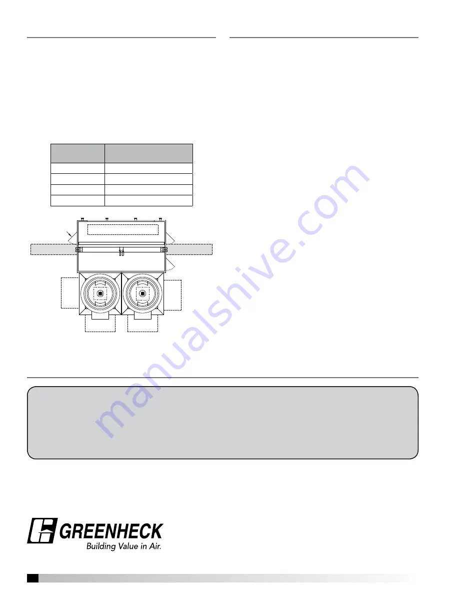
Coil Change Out Procedure

Coils can only be pulled out through the side of the 
plenum cabinet. Side panels which are nearest to the 
coil can be removed if the coil needs to be replaced. 
Size 020 ERS plenums only have a single coil and do 
not require coil removal clearances on both sides. If 
necessary, both coils can be removed through the 
same side of the plenum housing. This process would 
require the removal of an additional spacer panel that 
separates the two coils within the unit.

Cabinet 

Size

Minimum Clearance 

(inches)

020

114

030

74 (each side)

040

100 (each side)

060

132 (each side)

Date __________________ Time _____________ AM/PM
Notes:___________________________________________
_________________________________________________
_________________________________________________
_________________________________________________
_________________________________________________

Date __________________ Time _____________ AM/PM
Notes:___________________________________________
_________________________________________________
_________________________________________________
_________________________________________________
_________________________________________________

Date __________________ Time _____________ AM/PM
Notes:___________________________________________
_________________________________________________
_________________________________________________
_________________________________________________
_________________________________________________

Date __________________ Time _____________ AM/PM
Notes:___________________________________________
_________________________________________________
_________________________________________________
_________________________________________________
_________________________________________________

Maintenance Log 

Summary of Contents for ERS-MD

Page 1: ...oving parts as well as other potential hazards Other considerations may be required if high winds or seismic activity are present If more information is needed contact a licensed professional engineer before moving forward 1 Follow all local electrical and safety codes as well as the National Electrical Code NEC the National Fire Protection Agency NFPA where applicable Follow the Canadian Electric...

Page 2: ...For hard to reach internal surfaces or for occasional use consider using Tectyl 511M Rust Preventive or WD 40 or the equivalent Receiving Upon receiving the product check to make sure all items are accounted for by referencing the bill of lading to ensure all items were received Inspect each crate for shipping damage before accepting delivery Notify the carrier if any damage is noticed The carrier...

Page 3: ...d be used to identify and assemble the complete system Assembling systems with different identification tags can cause reductions in the fan s performance General Information To ensure a successful installation the instructions in this manual should be read and adhered to Failure to comply with proper installation procedures may void the warranty Pre Installation Checks Prior to fully assembling a...

Page 4: ...g to desired location 7 Never lift units in windy conditions 8 Preparation of curb and roof openings should be completed prior to lifting unit to the roof Verify the curb has the gasket seal on the top surface 9 Do not use fork lifts for handling unit Cabinet Size Cabinet Height Weight lbs 020 075 3700 090 4500 030 075 4300 090 4900 040 075 5400 090 6100 060 075 6900 090 7800 110 8300 Weights show...

Page 5: ...5 DRAIN LIFT LUG QTY 8 S S ISOLATION DAMPER Coil Coil Optional External Piping by others Service Doors Internal Pipe Chase Side or Bottom Intake Opening Lift Bracket Optional Internal Piping by others under Vektor fans Bypass Weatherhood s Vektor bypass air plenum optional mounting locations shown Filters Coil Coil Coil Service Doors Coil Service Clearance Coil Service Clearance Clearance Clearanc...

Page 6: ...the hardware kit attach the unit sections by bolting together frame extrusion from the inside Tighten the bolt washer assemblies to the top and both sides of the joining sections Start on the lower sides and work towards the top As the bolts are tightened the plenum sections will draw together Use anti seize gel to prevent galling welding of all stainless steel fasteners If necessary pull the unit...

Page 7: ...Contractor Installed Ductwork Energy Recovery Cabinet Energy Recovery Cabinet Roof Deck Curb Curb Roof Deck RECOMMENDED DUCT INSTALLATION FOR VEKTOR ENERGY RECOVERY VERTICAL INLETS NOTE ALL DUCT WORK AND HARDWARE SUPPLIED BY OTHERS CAULK AND OR GASKETING MATERIAL SHOULD BE USED TO SEAL DUCT TO VEKTOR ERS CABINET Contractor Installed Ductwork Contr actor Installed Ductwork Duct Connections Installa...

Page 8: ...ses steel toe boots and gloves are recommended during the installation and maintenance of the coil All field piping must be self supporting System piping should be flexible enough to allow for the thermal expansion and contraction of the coil Water Coil Installation Recommendations 1 Piping should be in accordance with accepted industry standards Always use a back up wrench on the coil connections...

Page 9: ... are located only in the coil plenum section Access is needed from both sides of the plenum to change all the filters Unit may have either 2 inch MERV 8 filters or 4 inch MERV 11 filters depending on the application requirements Use equivalent MERV rating filters when replacing Change the filters regularly Pressure drop readings can be used to determine when a filter should be replaced Prefilters ...

Page 10: ...es the pressure across the filter section Periodic inspection is necessary to determine whether filters need to be replaced Vapor Tight Lights Vapor tight lights provide light to each of the compartments in the energy recovery plenum The lights are wired to a junction box mounted on the outside of the unit The switch requires a separate power source to allow for power to the lights when the unit m...

Page 11: ...en working with coils Fin Straightening Coil fins may have been bent during shipping or servicing and should be straightened to maintain maximum heat transfer Reduction of the effective coil surface will correspondingly reduce coil capacity Always check fin appearance after any handling of the coil and after any servicing is done near the coils Fin combs are sized according to number of fins per i...

Page 12: ...over of Part 474118 Service Coil Change Out Procedure Coils can only be pulled out through the side of the plenum cabinet Side panels which are nearest to the coil can be removed if the coil needs to be replaced Size 020 ERS plenums only have a single coil and do not require coil removal clearances on both sides If necessary both coils can be removed through the same side of the plenum housing Thi...

Reviews: