background image

Pressure Drop Data 

FSDGB-211

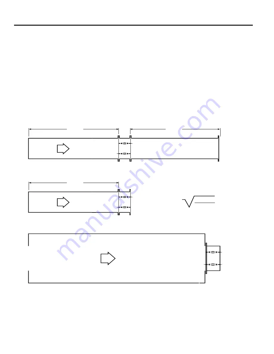
This pressure drop testing was conducted in accordance with AMCA Standard 500-D using the three configurations shown. All 

data has been corrected to represent standard air at a density of 1.201 kg/m3.

Actual pressure drop found in any HVAC system is a combination of many factors. This pressure drop information along with an 

analysis of other system influences should be used to estimate actual pressure losses for a damper installed in a given HVAC 

system.

AMCA Test Figures

Figure 5.3

 Illustrates a fully ducted damper. This configuration has the lowest pressure drop of the three test configurations 

because entrance and exit losses are minimized by straight duct runs upstream and downstream of the damper. 

Figure 5.2

 Illustrates a ducted damper exhausting air into an open area. This configuration has a lower pressure drop than 

Figure 5.5 because entrance losses are minimized by a straight duct run upstream of the damper.

Figure 5.5

 Illustrates a plenum mounted damper. This configuration has the highest pressure drop because of extremely high 

entrance and exit losses due to the sudden changes of area in the system.

5D

6D

5D

D

4 (W) (H)

3.14

Summary of Contents for Fire Smoke Dampers FSDGB-211

Page 1: ...mm 17 in high to maximize free area and performance Blades 1 24mm 16 ga galvanized steel reinforced with 3 longitudinal structurally designed vee s Seals Extruded silicone rubber blade seals Flexible stainless steel jamb seals Linkage Concealed in jamb Axles 12 7 mm 1 2 in dia plated steel Bearings Bronze sleeve type Fusible Link 280 C Size Limitations Minimum Size 204mm W x 152mm H 8 in W x 6 in ...

Page 2: ... AMCA Test Figures Figure 5 3 Illustrates a fully ducted damper This configuration has the lowest pressure drop of the three test configurations because entrance and exit losses are minimized by straight duct runs upstream and downstream of the damper Figure 5 2 Illustrates a ducted damper exhausting air into an open area This configuration has a lower pressure drop than Figure 5 5 because entranc...

Page 3: ... ratings only NN Y NN NN Y NN NN Y NN NN Y NN NN Y NN 13 4463 301 1 4 4 7 0 5 5 34 4 0 7 0 5 74 13 4463 301 Y Y Y Y Y 305mm x 305mm Velocity m s Pressure Drop Pa 2 5 10 5 1 35 7 7 80 10 135 12 6 207 15 5 311 17 8 411 20 8 561 610mm x 610mm Velocity m s Pressure Drop Pa 2 5 5 5 2 17 7 8 42 10 3 72 12 9 115 15 4 162 18 1 224 20 8 296 914mm x 914mm Velocity m s Pressure Drop Pa 2 6 3 5 1 10 7 6 22 10...

Page 4: ... 92 12 9 145 15 4 209 17 7 274 20 8 379 610mm x 610mm Velocity m s Pressure Drop Pa 2 5 3 5 10 7 7 22 10 3 40 12 8 62 15 5 92 17 9 122 20 8 167 914mm x 914mm Velocity m s Pressure Drop Pa 2 5 3 5 1 8 7 6 15 10 1 27 12 8 42 15 3 62 17 7 82 20 3 107 305mm x 1219mm Velocity m s Pressure Drop Pa 2 5 3 5 1 10 7 7 25 10 3 42 12 9 67 15 7 100 18 7 140 20 9 174 1219mm x 305mm Velocity m s Pressure Drop Pa...

Page 5: ...city m s Pressure Drop Pa 2 5 8 5 35 7 6 75 10 3 140 12 8 217 15 3 309 17 7 409 20 8 568 914mm x 914mm Velocity m s Pressure Drop Pa 2 5 8 5 1 30 7 7 67 10 2 115 12 9 184 15 5 269 18 1 354 20 6 471 305mm x 1219mm Velocity m s Pressure Drop Pa 2 6 8 5 1 32 7 7 75 10 2 130 12 7 202 15 5 301 18 1 416 20 6 536 1219mm x 305mm Velocity m s Pressure Drop Pa 2 5 1 5 42 7 7 95 10 3 172 12 7 264 15 3 381 17...

Page 6: ...ed steel 3V type with three longitudinal grooves for reinforcement Damper frame shall be galvanized steel formed into a structural hat channel shape with reinforced corners Bearings shall be sintered bronze sleeve type rotating in extruded holes in the damper frame Blade edge seals shall be silicone rubber designed to inflate and provide a tighter seal against leakage as pressure on either side of...

Reviews: