Model IGX Make-Up Air
16
®
Evaporative Cooling Module
Note: Small evaporative cooling module will ship
attached to the base unit from the factory and will
not require any additional fixation to the base unit as
illustrated below.
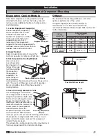
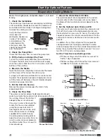
1. Locate Equipment Support(s)
Position equipment support(s)
on the roof (reference the unit
submittal for placement of
equipment support(s) in relation
to the unit). Verify that all unit
supports are level, shim if
necessary. Attach equipment
support to the roof using appropriate
methods, remove metal cover, flash to
wooden nailer and reinstall cover.
2. Apply Sealant
Apply an appropriate sealant around the
airstream opening to create an airtight seal.
3. Set Evaporative Cooling Module
Use a crane and
a set of spreader
bars hooked to the
factory lifting lugs
to lift and position
the module on
the equipment
support(s). The
cover flange on
the evaporative
cooling module should overlap the cover flange on the
unit. The use of all lifting lugs and a set of spreader
bars is mandatory when lifting the evaporative
cooling module.
4. Secure Cooling Module to Unit
Use self-tapping screws to fasten
the cooling module to the base unit
along the top and down both sides.
Fasten at the top through the cover
flanges. To fasten the sides, the
media may need to be removed. To
remove the media, first remove the
access panel on the evaporative
module and disconnect the
evaporative pump(s). The media
will now slide out. With the media
removed, you can access the side fastening points inside
the evaporative cooling module. With all the screws in
place, reinstall the media, reconnect the pumps and
reinstall the access panel.
The evaporative cooling module must be mounted level
to ensure proper operation and water drainage.
Metal Cover
Equipment
Support
Equipment Support
Placing Evaporative Module
Sealant
Sealant
Securing Evaporative
Module
Diffuser
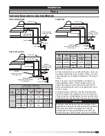
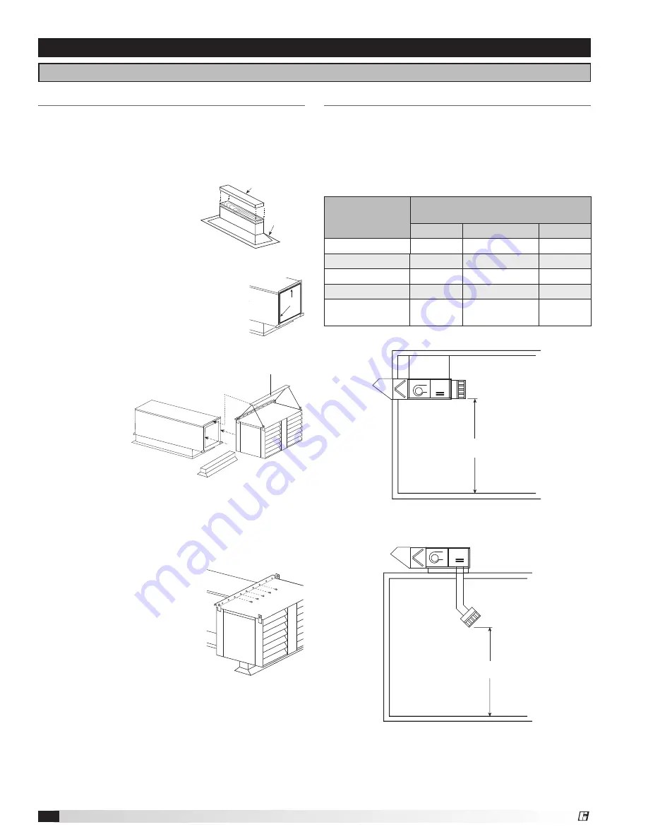
The location of the discharge diffuser is critical for
optimum performance of the system.
Using self-tapping screws, attach diffuser to
the ductwork or unit. Be sure to maintain the
recommended floor to diffuser height. Refer to the chart
for this information.
Installation
Optional Component Mounting
Indoor Mounted
Unit
h
Thru-Wall Diffuser Height
Rooftop
Unit
h
Rooftop Diffuser Height
Airflow
cfm (m
3
/s)
Diffuser Height
feet (m)
Minimum
Recommended Maximum
4,000 (2)
15 (5)
20 (6)
25 (8)
6,000 (3)
15 (5)
20 (6)
25 (8)
8,000 (4)
20 (6)
20-25 (6 - 8)
30 (9)
10,000 (5)
20 (6)
20-25 (6 - 8)
35 (11)
13,000 or greater
(6 or greater)
25 (8)
30-35 (9 - 11)
40 (12)


