Model IGX Make-Up Air
44
®
Troubleshooting
Evaporative Cooling
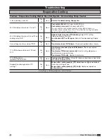
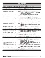
Problem: Evaporative Cooling Module Does Not Operate - Auto Drain and Fill Control
Is fan operating correctly?
Yes
È
No
Æ
Refer to the Troubleshooting, Supply Fan.
24 VAC between terminals Y1 and C
Yes
È
No
Æ
Cool switch (S4) off.
Turn cool switch (S4) on.
Cool switch not wired
. Wire cool switch (S4).
If a cool switch is not required and a cooing inlet air sensor is
provided, place jumper from R to Y1 to allow the cooling to enable
based on the cooling inlet air sensor.
24 VAC between terminal A2 and A1
on cooling relay (RC)?
Yes
È
No
Æ
Optional inlet air sensor (TS4) holding.
Adjust TS4 setting.
Reference Supply Fan, Start-Up.
Fan Interlock (ST1 or RF) open.
Refer to Troubleshooting, Supply
Fan.
24 VAC between terminals 62 and 61?
Yes
È
No
Æ
Auto drain transformer TR2 circuit breaker tripped.
Reset
transformer circuit breaker. If circuit breaker continues to trip, inspect
circuit for improper wiring or grounding.
Auto drain transformer TR2 failed.
Replace auto drain transformer.
24 VAC between terminals 7 and 61?
Yes
È
No
Æ
Inlet air temperature below evap freeze protection sensor (FRZ)
set point.
Allow inlet air temperature to rise above 55ºF.
Evap freeze protection sensor (FRZ) not wired.
Wire evap freeze
protection sensor.
Evap freeze protection sensor (FRZ) failed.
Replace evap freeze
protection sensor.
Time ranges on auto drain timer set
correctly?
Yes
È
No
Æ
Set time ranges to the values shown on the ladder diagram.
Auto drain timer in drain mode?
No
È
Yes
Æ
Wait for the drain mode timer to expire (usually 10 minutes).
24 VAC between terminals 8 and 61?
Yes
È
No
Æ
Auto drain timer (TC) wiring issue.
Inspect and correct wiring issue.
Auto drain timer (TC) faulty.
Replace auto drain timer.
Evaporative cooling module sump
filled?
Yes
È
No
Æ
Auto drain valves (VS,VD,VSD) not wired.
Wire auto drain valves.
Auto drain valve(s) failed.
Replace failed valve(s).
24 VAC between terminals A2 and A1
on RA relay?
Yes
È
No
Æ
Wiring issue to RA relay.
Inspect and correct wiring.
Line voltage at primary side of TR3?
Yes
È
No
Æ
Transformer fuses (FU7) blown.
Check and replace blown fuse(s).
115 VAC between terminals 102 and
101?
Yes
È
No
Æ
Transformer secondary fuses (FU8) blown.
Check and replace
blown fuse(s).
Transformer TR3 wired incorrectly.
Refer to wiring diagram on
transformer and correct wiring.
Transformer TR3 faulty.
Replace transformer.
115 VAC between terminal 14 on RC
relay and 101?
Yes
È
No
Æ
Auto drain relay (RA) failure.
Check for loose connections or bent
relay pins, repair or replace relay.
115 VAC between terminals 116 and
101?
Yes
È
No
Æ
Cooling relay (RC) failure.
Check for loose connections or bent relay
pins, repair or replace relay.
Evaporative cooling pump(s) (P1)
running?
Yes
È
No
Æ
Evaporative cooling pump(s) (P1) wired incorrectly or not wired.
Correct any wiring Issues.
Evaporative cooling pump(s) (P1) faulty.
Replace evaporative
cooling pump(s).
Everything is working properly, consult factory.

