6
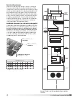
VersiVent Energy Recovery Ventilator
Unit
Size
A
B
C*
D
E
F
W
L*
Curb Weight^
(lbs.)
C1
C2
C3
C4
VER-45
28.146
44.627
30.159
36.159
44.159
50.275
36.312
47.571
27.909
69.987
see
note
447
VER-65
30.825
46.597
30.159
36.159
44.159
50.275
38.124
47.571
27.909
76.246
473
VER-90
34.825
85.658
30.159
36.159
44.159
50.275
41.312
47.571
27.909
91.010
621
All dimensions shown in inches.
L* — Sum up the applicable section dimensions (A–F) for your unit to get the overall length.
^ — Curb weights shown are for the worst case scenario (largest curb) possible for each size unit.
4-inch Final Filters
2-inch Filters
2-inch Filters
Wheel Cassette
Outdoor Air
We
atherhood
Intake
Section
Wheel
Section
Optional
Coil Section
Blower
Section
Optional
IG Heater Section
Optional
Condensing Section
Condensing Coil
Drain Pan Connection
IG Gas Connection
ELEVATION
VIEW
A
B
C*
D
L*
E
F
Curb Outside Dimensions and Weights
Curb Cap Details
Side of Unit
Recommended
2-inches of
Insulation
Roof Curb
1 in.
1 in.
2½ in.
1.195 in.
1 in.
C* Coil Module Options
C1
C2
C3
C4
HW
HW + DX
CW + HP
HW + CW + HP
CW
HW + CW
DX + HP
HW + DX + HP
DX
EH + CW
DX + HGRH
EH + DX + HP
EH
EH + DX
DX + HW + HGRH
EH + CW + HP
DX + EH + HGRH
HW = Hot Water
EH = Electric Heat
CW = Chilled Water
HP = Wrap-around Heat Pipe
DX = Direct Expansion
HGRH = Hot Gas Reheat
Elevation View
W - 3.75 inches
L* - 3.75 inches
Subtract 3.75 inches from dimensions
W & L* to get the outside curb dimensions.
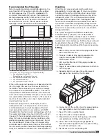
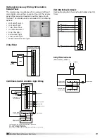
Most factory-supplied electrical components are pre-
wired. To determine what electrical accessories require
additional field wiring, refer to the unit-specific wiring
diagram located on the inside of the unit control center
access door. The low voltage control circuit is 24 VAC
and control wiring should not exceed 0.75 ohms.
Control wires should not be run inside the same conduit
as that carrying the supply power. Make sure that field-
supplied conduit does not interfere with access panel
operation.
If wire resistance exceeds 0.75 ohms, an industrial-style
plug-in relay should be added to the unit control center
and wired in lieu of the remote switch (typically between
terminal blocks R and G on the terminal strip (refer to
Typical Control Center Components). The relay must be
rated for at least 5 amps and have a 24 VAC coil. Failure
to comply with these guidelines may cause motor
starters to “chatter” or not pull in which can cause
contactor failures and/or motor failures.
Note: Standard factory-installed electric post-heaters
have their own disconnect separate from the
unit disconnect. Thus, each electric post-heater
requires its own separate power connection.


