24
ROOF VENT ASSEMBLY
V
W
X
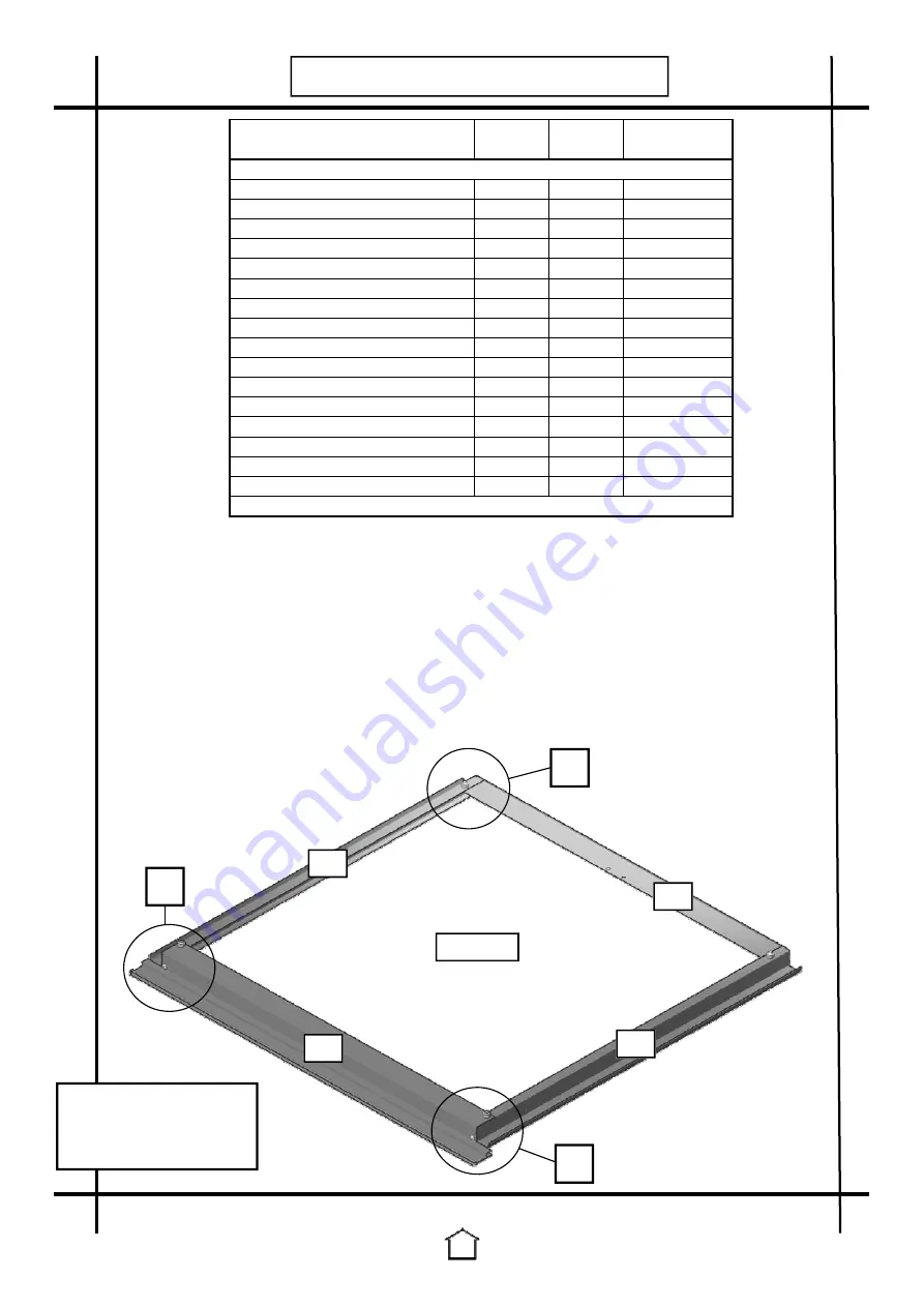
This image is a view of the
underside of the vent.
(This is the best position to
build the vent in).
540
541
541
543
610 X 610
Part Name
Part Length
Qty Required
No.
mm
\ vent
Casement stay*
330
-
1
Vent - bottom
540
590
1
Vent - side
541
604
2
Vent - slam bar
542
645
1
Vent - top
543
650
1
Bolt, square head - 10mm M6
576
10
4
Nut - M4*
578
-
6
Nut - M6
579
-
6
Nut caps
580
-
6
Screws, self tapping - 19mm M3.5
583
19
4
Silicone, gun
584
-
1
Silicone, tube
585
-
1
Screws, countersunk - 10mm M4*
587
10
6
Bolt, Cropped Head - 10mm M6
589
10
2
Vent peg assembly
709
-
2
Toughened Glass 610
-
610 X 610
1
*Redundant if an autovent is being used
1.
(Ignore step 1 if you are using an Autovent). Attach the casement stay to the vent bottom
using the M4 countersunk screws and nuts.
2.
Lay the components out so the underside of the vent is facing up. Lightly bolt the vent
sides to the vent top. (Diagram V & X)
3.
Now use the self tapping screws to screw through the vent top into the screw channel on
the vent sides. (Diagram V)
4.
Slide the 610 X 610 glass into the channels in the vent sides. Push the glass all the way up
the channels until it slots into the vent top. (Diagram W2)
5.
Bolt the vent bottom on to secure the glass. (Diagram W1)
6.
Now tighten all the bolts.
7.
Trim the end off the silicone tube. Run a bead of silicone all the way round edge of the
glass on the outside of the vent. This will help to reduce any leaks and will also secure the
glass.
8.
Repeat for each vent.
9.
The slam bar listed in the table
above is fitted during the vent
installation on page 34.


