30
LOUVRE ASSEMBLY
Y
Z
AA
BB
Part Name
Part Length
Qty
No.
mm
Required
Top/Bottom cill
-
592
2
Side bar
-
444
1
Side bar - with handle
-
444
1
Screws, self tapping - 10mm M4
-
19
4
Crop head bolts - 10mm M6
-
10
4
Nuts - M6
-
-
4
Toughened glass (L)
-
573 X 100
5
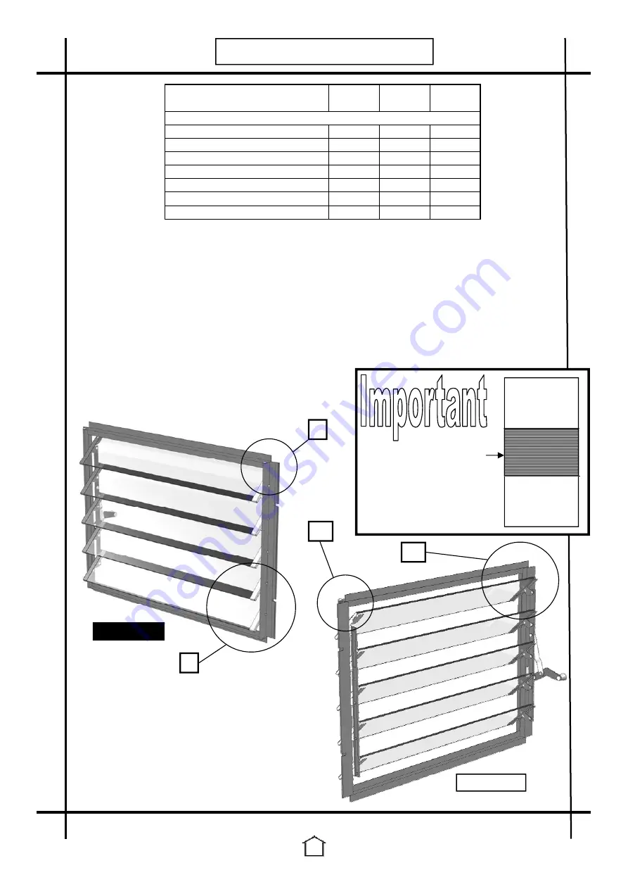
1. Trim rubber to side lengths and place top and bottom cill into position on side bars.
Secure with self tapping screws. (Diagrams Y & AA)
2. Repeat this process on each corner.
3. When you are fitting your louvre the pane of glass (610 X 457) must be inserted below
it first.
4. Use your four crop headed bolts to attach the louvre to your side glazing bars
(Diagram Z). You will
NOT
need
glazing separators
above and below the louvre.
The glass simply butts right up to the metal.
5. Pinch glass holding clips together prior to glazing to help secure the glass blades
tightly. (Diagram BB)
6. Insert each of the five glass blades.
Louvre
Contains
5
x
573 x 100mm
Note that louvre must be
positioned between the
two panes not at top or
bottom.
GLASS
610 X 759
GLASS
610 X 457
Internal view
External view


