32
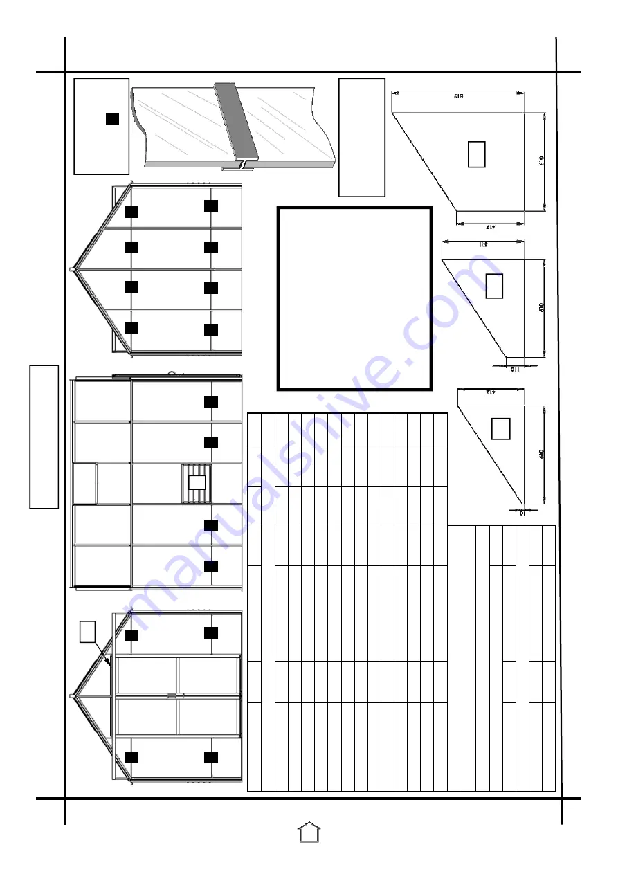
GLASS
PLAN
V
C
C
C
C
C
B
B
B
C
C
B
B
B
B
B
Q
Q
Q
A
R
EE
EE
EE
EE
FF
DD
DD
L
EE
CC
Glazi
ng
sepa
rator
(559
)
=
H
H
H
H
H
H
H
H
H
H
H
H
H
The
sh
ort
flan
ge
sh
ould
be
on
the
out
side
of
the
building
fa
cin
g
upward.
FF
557
(Diagram
show
ing
the
lay
out
f
or
a
8
X
1
0 G
re
en
ho
us
e)
C
Q
B
H
DD
DD
H
H
C
C
B
H
B
FF
CC
Part
Name
Part
No.
Size
(mm
)
8
X
6
8
X
8
8
X
10
8
X
12
A
-
610
X
610
1
2
3
4
B
-
610
X
457
12
14
16
18
L
-
573
X
100
5
10
10
10
C
-
610
X
1210
11
12
14
16
Q
-
610
X
1520
5
6
7
8
R
-
610
X
917
1
2
3
4
V
-
610
X
759
1
2
2
2
DD
-
563
X
880
4
4
4
4
EE
-
610
X
412
X
10
4
4
4
4
CC
-
610
X
511
X
110
2
2
2
2
FF
-
610
X
819
X
417
2
2
2
2
Glass
Jack
557
590
X
33
2
2
2
2
Glazi
ng
Sepa
rator
559
610
X
15
16
18
20
22
EXTRA
LOU
V
RE
WIN
D
O
W
Situated
at
side
or
rear
ce
nter.
For
on
e
louvre
remove:
Qty
C
-
610
X
1210
1
And
add:
L
-
573
X
100
5
V
-
610
X
759
1
CC
For
Peak
models
with
kick
panels:
C
b
ec
om
es
6
10
x1
50
0
B
be
come
s
the
alumini
um
kick
pan
el.
No
pla
stic
gl
az
ing
sep
arato
r
is
need
ed
bet
ween
the
two.
Louvre
m
ake
up
pan
e
V
ch
ange
s
to
two
pan
es:
(o
ne
above
and
one
be-
low
louvre:
610x
153
bel
ow
and
a
610x89
3
abo
ve.)


