background image

881MBTS

13

52094216 REV 0

© 2021 Greenlee Tools, Inc.

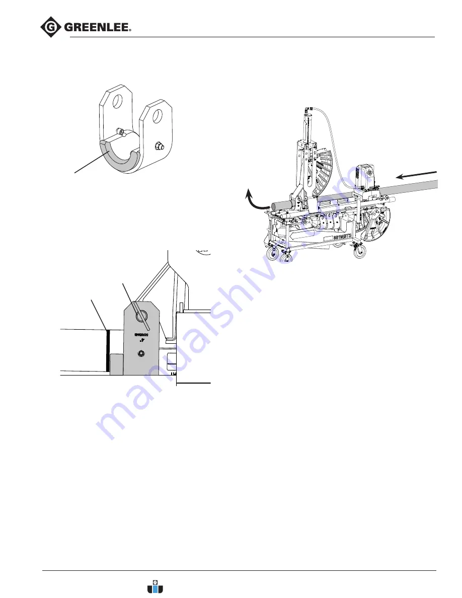
Figure 14

Figure 15

6.  Slide the conduit through the front of the saddle and 

shoe, or the saddle can be pinned to the shoe after 

the conduit is in position. Position the conduit so 

the bending mark is aligned with the outer edge of 

the saddle lip. (Fig. 15)

7.  With the chain vise as close to the conduit track 

couplings as possible, “snug up” the unit by 

keeping the saddle and follow bar tight against the 

carriage and advance the ram until the conduit, 

shoe and saddle fit tightly together. 

8.  Clamp the rear end of the conduit in the vise by 

securing the chain over the conduit and turning the 

handle until tight. 

Saddle Lip

Bend Mark

9.  Bend conduit to desired angle, follow the operating 

instructions in the 980 series hydraulic pump 
instructions. The follow bar and vise will travel with 
the conduit as it bends. Do not over travel the follow 
bar (Fig. 16).

Figure 16

Bend Direction

Saddle

Pin

5.  Pin the matching saddle to the front of the shoe with 

the saddle lip facing away from the bender forks 
(Fig. 14).

www.calcert.com

sales@calcert.com

1.800.544.2843

0

5

10

15

20

25

30

Summary of Contents for 783310064985

Page 1: ...MANUAL Mobile Bending Table for 881 Hydraulic Bender Read and understand all of the instructions and safety information in this manual before operating or servicing this tool KEEP THIS MANUAL www calcert com sales calcert com 1 800 544 2843 0 5 10 15 20 25 30 ...

Page 2: ...ty Information 4 Greenlee Contact Information 4 Tool Description 5 Specifications 5 Tool Identification 6 Decals Locations 7 Training Qualification 9 Pre Operation Inspection 9 Work Area Tool Set Up 9 Bending Procedure 11 Security 14 Transportation 15 Replacement Parts Kits 16 Disposal 16 www calcert com sales calcert com 1 800 544 2843 0 5 10 15 20 25 30 ...

Page 3: ...roperty damage This symbol means always wear safety glasses with side shields or goggles when handling or using this equipment to reduce the risk of eye injury This symbol means read the operator s manual carefully before using the equipment The operator s manual contains important information on the safe and proper operation of the equipment This symbol means be careful lifting object is heavy Th...

Page 4: ...r hair clothing and gloves away from moving parts Loose clothes jewelry or long hair can be caught in moving parts Keep bystanders a safe distance from the work area Additional people close to the operator increases the risk of injury to themselves and the operator from distraction or interaction with equipment Keep work area clean and well lit Cluttered or dark areas invite accidents Use this equ...

Page 5: ...sories attached Chain vise for securing conduit Protractor for checking bends Swivel tray with pendant holder for hydraulic pump Specifications Weight MBTS w pump tray and vise 355 lb 161 kg Weight MBTS w 980 series pump bender and accessories 1190 lb 540 kg Dimensions MBTS w pump tray 80 0 in x 30 9 in x 41 9 in 203 2 cm x 78 5 cm x 106 4 cm Dimensions Maximum Operating Footprint 80 0 in x 42 5 i...

Page 6: ... Storage 11 3 Shoe Storage 12 4 Shoe Storage 13 Pump Tray Pendant Holder 14 Fork Pockets 15 Conduit Rails 16 Conduit Collars 17 Bender Carriage 18 Carriage Latches 19 Chain Vise 20 Tablet Notebook Tray 21 Electrical Cord Wrap 22 Shipping Strap Holes 23 Caster Rigid 24 Caster Swivel 25 90 Coupler 26 Ram Positioner 27 Protractor 1 5 6 22 7 3 9 13 4 8 2 20 21 15 18 17 11 12 14 10 19 24 23 25 26 27 16...

Page 7: ...legible and replace when necessary G F J A 3 0 1 5 52093744 REV 0 52093744 REV 0 Color Black Material Polycoated vinyl per ES 788 4x 0 25 B 3 0 1 5 52093745 REV 0 52093745 REV 0 Color Black Material Polycoated vinyl per ES 788 4x 0 25 50 lb 22 kg C 3 0 1 5 52093746 REV 0 52093746 REV 0 Color Black Material Polycoated vinyl per ES 788 4x 0 25 50 lb 22 kg D 3 0 1 5 52093747 REV 0 52093747 REV 0 Colo...

Page 8: ...4216 REV 0 8 2021 Greenlee Tools Inc Decals Markings Locations cont d Keep all decals clean and legible and replace when necessary H I J K L M F G www calcert com sales calcert com 1 800 544 2843 0 5 10 15 20 25 30 ...

Page 9: ...ment and space for the operator to work comfortably and according to tool operating instructions to reduce the risk of injury Clearly marked or easily recognizable to prevent people from coming into the area while the tool is being used Barriers or cones around work site are ways to do this 2 Inspect the work to be done Determine the correct equipment and accessories for the job 3 Confirm all rela...

Page 10: ...m into the vertical bending position and lock the forks in place by revolving and pinning the carriage latches in place Fig 4 10 Pin the yoke to the ram piston with the spring clip Fig 5 11 Place a 900 series hydraulic pump in the pump basket so the front of the pump is facing away from the pivot Store the pendant in the holder on the basket when not in use The pump reservoir should be fastened to...

Page 11: ...ion Do not stand in a direct line with the follow bar while bending The follow bar is under high pressure during use and has potential to propel forward rapidly Adjusting Ram Position The ram positioner is used to adjust the position of the ram within the connecting forks while in the vertical position Fig 9 1 To attach the ram positioner to the yoke first rotate the yoke 90 from normal bending po...

Page 12: ...rting the follow bar secure the ram and lift the forks back into position 3 Place the matching shoe on the follow bar with the saddle connection closest to the START end 4 Lower the piston and yoke until it is aligned with the EMT or IMC Rigid yoke connection on the shoe then pin in place Fig 13 EMT Yoke Connection IMC Rigid Yoke Connection START Conduit Groove Bend Set Up Follow Bar Ears Saddle C...

Page 13: ...ge and advance the ram until the conduit shoe and saddle fit tightly together 8 Clamp the rear end of the conduit in the vise by securing the chain over the conduit and turning the handle until tight Saddle Lip Bend Mark 9 Bend conduit to desired angle follow the operating instructions in the 980 series hydraulic pump instructions The follow bar and vise will travel with the conduit as it bends Do...

Page 14: ...locked on the three holes Fig 20 in front of the misc storage shelf Padlock Hinged Plate Padlock Figure 19 Figure 17 Security The MBTS has security features to secure bending accessories when transporting or storing The padlock pockets are identified by the lock cutout on the cart The latches are for No 1 or No 5 Master Lock or equivalent sized padlocks not included with purchase The 3 in 3 1 2 in...

Page 15: ...orks This position is easiest for the operator to lay the ram down and keeps the ram from sticking out over the back of the table 4 Unpin the carriage latches and carefully lower the ram onto the chain vise 5 Clamp the ram body in the chain vise Fig 21 Do not use the 90 coupler as a handle or allow it to lay on the vise or the coupler could be damaged When using a forklift the carriage must be mov...

Page 16: ...t D Bolt Hex 1 2 13 X 7 8in L E Screw Flng 3 8 16 X 1in L F Nut Flange Nylock 3 8 16 A Magnet Carriage B Screw BTN HD M4 C Pin 1 2 in D D Lanyard E Bolt Hex 1 2 13 X 1 1 4in L Disposal 2B 2A 2C 2D 2E 1 Fasteners Kit MBT 1E 1A B 1F Cat Description 14064G CASTER RIGID 14065G CASTER SWIVEL LOCKING 14066G FASTENERS KIT MBT 14067G DECAL KIT 14092G RAM POSITIONER 14093G 90 COUPLER 14068G CARRIAGE 14069G...

Page 17: ...ler Kit 4 Axel Roller Kit A Retaining Ring B Washer 3 4 in ID C Axel D Roller Straight 5 Foot Kit A Foot B Screw Cap 1 4 in C Nut Locking 1 4 in 6 Screw Handle Kit A Screw Unit Chain B Handle Assy C Screw BTN HD 1 4 in D Washer 1 4 in ID 6B 6C D 5B 5A 3A 3C 6A 4D 4B 4A 4C 3B D www calcert com sales calcert com 1 800 544 2843 0 5 10 15 20 25 30 ...

Reviews: