93-602
9
1.
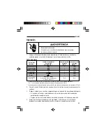
Set the selector according to the Settings Table and connect the test leads to the unit.
Start with the highest measurement range.
Settings Table
To measure
set the selector
connect the
and connect the
this value …
to this function …
red lead to …
black lead to …
DC Voltage
DCV
+
COM
AC Voltage
ACV
+
COM
DC Current
DCA
+
COM
Resistance
Ω
+
COM
Continuity*
200
+
COM
Diode**
+
COM
Transistor Gain***
h
FE
(
PNP
or
NPN
)
N/A
N/A
Set to match transistor type.
* Continuous tone indicates circuit resistance is less than approximately 80
Ω
.
** A “1” in the left-most column indicates that the diode is reverse biased.
*** Insert the legs of the transistor (emitter, base and collector) so that they correspond to
the terminals (E, B and C).
2.
See Typical Measurements for illustrations of typical uses.
3.
Test the unit on a known functioning circuit or component.
• If the unit does not function as expected on a known functioning circuit, replace the battery.
• If the unit still does not function as expected, send the unit to Greenlee for repair.
4.
Take the reading from the circuit to be tested. If the resolution is not satisfactory, remove
the leads from the circuit and change to the next lower range.
Electric shock hazard:
Contact with live circuits can result in severe injury or death.
Operation

