Greenlee Textron / Subsidiary of Textron Inc.
14
4455 Boeing Dr., Rockford, IL 61109-2988 815/397-7070
HG3505A / 42303 Portable Power Unit
Note: During disassembly, take special note of the
position of the wear plate (5) and pressure
loading seals (6 & 14). The open side of the
seals should be toward the inlet side of pump.
The gear contact pattern in the bore is additional
identification of the inlet side.
9.
Invert pump body with shaft seal (8) up. Remove
shaft seal by prying it out with a large screwdriver.
Damaging the shaft seal bore will result in seal
leakage.
10. Wash all parts and dry thoroughly.
11. Inspect wear plate (5) and replace if scoring or
uneven wear is observed. A somewhat heavier
wear pattern is normal on the inlet side of the wear
plate, but there should be no heavy scoring in this
area.
12. Inspect bushings in body and cover. Replace cover
or body if bushings are heavily scored or burned.
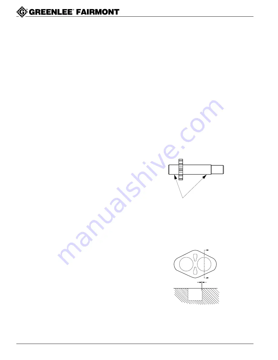
13. Inspect gear journals and faces. Replace if faces or
journals are scored or worn, or if shaft journal wear
exceeds 0.001 inch (.025 mm).
Disassembly
Pump disassembly should be done only if trouble-
shooting indicates that the pump is not operating
properly. Overhaul pump only in a clean, dust-free
location, using clean tools and equipment. Dirt or grit
will damage the highly machined surfaces and will result
in leakage or premature failure of the pump.
Before beginning disassembly, scribe a mark on inlet
side of the body and the cover to insure that the pump
will be reassembled in the same manner as it was
shipped from the factory. If the body or the cover is
replaced during overhaul, scribe a mark on the new part
in the same location as the mark on the part it replaces.
Reference numbers refer to items illustrations listed.
1.
See Exploded View, HG3505 Power Unit. Drain
the hydraulic system and remove reservoir. Filter
should be removed and cleaned whenever reservoir
is removed. Loosen nut of male connector (9) and
turn tube (27) aside. Remove baffle (30).
Note: Do not adjust the hex nuts and washers located
on studs (29).
2.
Remove swivel nut of hose assembly (32) from
elbow (33), leaving elbow in place. Remove hex
head cap screws (19) and washers from pump
flanges. Spacers (18) may fall free. Loosen set
screw (16) which secures the pump shaft to the
coupler (15). It is not necessary to loosen the two
set screws (16) which secure the engine output
shaft to the coupler. Remove pump from power unit.
3.
See Exploded View, Pump. Clean outside of pump
with a good grade solvent and dry thoroughly.
4.
Remove Woodruff key (9) from drive shaft. Using a
file or stone, remove any burrs from shaft end or
keyway. Grease keyway before sliding drive shaft
through shaft seal.
5.
Secure pump in vise with shaft end down, using
light clamping pressure. Remove cap screws (1)
and washers (2). Remove pump from vise.
6.
When separating the body from the cover, use one
hand to support cover from underneath, since cover
and internal parts will drop suddenly when dowel
pins are disengaged. Separate cover (10) from
body (13) by supporting pump, shaft end up, on the
mounting flanges and pressing on end of drive shaft
with an arbor press. OR use two large screwdrivers
to pry in the indented areas between body and
cover, OR tap drive shaft lightly with a plastic mallet.
Note: Do not insert screwdrivers further into the pump
than the depth of the indentations. Any burrs or
scratches must be removed from the body and/or
cover after this procedure to assure a good seal
between body and cover.
7.
Holding pump with shaft end down, remove cover
(10). Dowel pins (7) and seal ring (4) may remain
either in the body or cover.
8.
Lift out; driven gear (11), drive gear (12), and wear
plate (5).
JOURNAL WEAR IN
BEARING AREA
14. Inspect body for wear and scoring. If gear contact
wear on the inlet side exceeds 0.005 inch (.127
mm), replace body. If the body is usable, remove
any burrs with suitable burring tool.
A
A
IN
OUT
.005
SECTION A-A


