background image

Greenlee Textron / Subsidiary of Textron Inc.

17

4455 Boeing Dr., Rockford, IL 61109-2988   815/397-7070

HG3505A / 42303 Portable Power Unit

Parts List

UPC NO.

KEY

78-3310-

PART NO.

DESCRIPTION

QTY

1

44111

F022608

Engine, Kawasaki ...................................... 1

3

41969

F022609

Rubber Mount ........................................... 4

4

41256

F001213

Cap Screw, Hex Head 1/4-20 x 1-1/4

Zinc-Plated ........................................... 4

5

41291

F007022

Hex Nut, 1/4-20 Zinc-Plated ..................... 10

6

41174

140328

Oil Cooler with tubing (includes #7) .......... 1

7

42130

42130

Trim (included in #6) ................................. 1

8

42081

F023752

Cap Screw, Hex Head 1/4-20 x 2

Zinc-Plated ........................................... 2

9

41319

F010175

Male Connector with Nut ........................... 4

10

40855

134327

Manifold ..................................................... 1

11

43244

F001875

O-Ring, 3/8 x 9/16 x 3/32-70 ..................... 4

12

41971

F002611

O-Ring, 1-15/16 x 2-1/8 x 3/32-70 ............ 1

13

41456

F014099

Cap Screw, Socket Head 5/16-24 x 3/4 .... 2

14

44108

44108

Key ............................................................ 1

15

44112

134328

Coupler ...................................................... 1

16

41362

F011592

Set Screw, #10-24 NC-3 x 1-1/4 ............... 3

17

41972

F022612

Pump (see Exploded View, Pump) ........... 1

18

44113

134329

Spacer ....................................................... 2

19

44114

F022613

Cap Screw, Hex Head 5/16-24 x 5

Zinc-Plated ........................................... 2

20

41973

F022614

FILTER ...................................................... 1

21

41397

F012813

O-Ring, .644 x .818 x .087-90 ............. 1

22

41974

F022615

Breather/Filler Plug ................................... 1

23

41975

F022616

Bypass Valve ............................................ 1

43318

43318

Replacement Seal Kit .......................... 1

24

44115

F022617

Elbow, 90

°

 3/8 MNPT x 3/8 FNPT ............ 2

25

41692

F018353

Level Seal Plug, 1/4 NPTF ........................ 1

26

41976

F022618

Relief Valve - 1400 PSI ............................. 1

27

44116

134331

Tube .......................................................... 1

28

44117

134333

Tube .......................................................... 1

29

40856

134334

Stud ........................................................... 2

30

44118

134335

Baffle ......................................................... 1

31

41380

F012056

Adapter, 9/16-18 JIC x 3/8 MNPTF ........... 1

32

40857

134336

Hose Assembly - 19.5" - 9/16-18

JIC union each end .............................. 1

33

41414

F013327

Elbow - 90

°

 9/16-18 JIC x 9/16-18

M. Str. Thd ........................................... 1

41353

F011302

Replacement O-Ring

.468 x .624 x .078-90 ........................... 1

34

41977

F022621

O-Ring, 6-1/2 x 6-11/16 x 3/32-70 ............ 1

36

42120

42120

Screen ....................................................... 1

37

42956

134338

Spacer ....................................................... 2

38

40858

134339K

Reservoir ................................................... 1

39

41978

F022625

Washer, Self-Sealing ................................ 2

40

41323

F010506

Cap Nut, 1/4-20 UNC-28 ........................... 2

41

41348

F011169

Pipe Plug, 3/8 NPTF ................................. 1

42

41979

F022626

Sight Check Gauge ................................... 1

40891

135326

Decal - DANGER (STOP ENGINE) .......... 1

44752

44752

Decal - I.D. ................................................ 1

Summary of Contents for Fairmont 42303

Page 1: ...UCTION MANUAL PORTABLE HYDRAULIC POWER UNIT HG3505A 42303 Read and understand this material before operating or servicing this equipment Failure to understand how to safely operate this tool could result in an accident causing serious injury or death ...

Page 2: ...bleshooting 13 Disassembly 14 Assembly 15 HG3505A Power Unit Exploded View 16 Parts List 17 Pump 18 Optional Accessories 19 Appendix A SAE J1273 May 1986 20 21 Description The HG3505A Portable Hydraulic Power Unit is compact efficient and quiet Because it is completely portable and self contained it can be used at almost any job site Additional or replacement manuals may be obtained from your Gree...

Page 3: ...sed to call your attention to instructions concerning your personal safety Watch for this symbol It points out important safety precautions It means ATTENTION Become alert Your personal safety is involved Read the message that follows and be alert to the possibility of personal injury or death Immediate hazards which if not avoided WILL result in severe personal injury or death SAFETY ALERT SYMBOL...

Page 4: ... engine fan Engine exhaust system pump etc may be hot Use caution when working around power unit Hot surfaces can cause serious burns Do not let the power unit engine run unattended The engine must be monitored so that it can be shut down immediately in case of a malfunction Failure to observe these warnings could result in severe injury or death Stop engine before filling fuel tank Do not fill fu...

Page 5: ...are rated for 100 lbs 46 kg and are securely attached between the power unit and lifting equipment Inadequate components may fail and cause the power unit to fall resulting in injury or property damage Note Keep all decals clean and legible Replace decals when necessary with new decals listed in the Parts section of this manual IMPORTANT SAFETY INSTRUCTIONS Specifications Height 18 25 in 46 4 cm L...

Page 6: ...3 8 hoses for the pressure line Using hoses over 25 in length will cause a decrease in power to the tool Electrical Shock Hazard When utilizing this tool near energized electrical lines select and maintain the hydraulic fluid to meet the minimum dielectric standards required by your safety department Failure to observe this warning could result in severe injury or death Recommended Hydraulic Fluid...

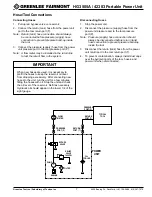
Page 7: ...ssure port to the tool pressure port P Note Pressure supply hose connection should always be disconnected before return tank hose connection to prevent pressure build up inside the tool 3 Disconnect the return tank hose from the power unit return port to the tool return port T 4 To prevent contamination always install dust caps over the hydraulic ports of the tool hoses and power unit when disconn...

Page 8: ... hands to check for leaks Depressurize hydraulic system before servicing Do not disconnect tool hoses or fittings while the power unit is running or if the hydraulic fluid is hot Exposure to hot hydraulic fluid can cause serious burns Wear eye protection when operating this tool Failure to wear eye protection can result in serious eye injury from flying debris or hydraulic oil Do not run the power...

Page 9: ... 5 After the engine has started return the choke lever to the OPEN position and allow the engine to warm up for 3 5 minutes without moving the throttle lever The efficiency of any hydraulic unit will be reduced in cold weather if the unit is operated with cold oil It is recommended that the power unit be allowed to warm up before operating any tool 6 After the engine is warmed up engine speed can ...

Page 10: ... Inc 10 4455 Boeing Dr Rockford IL 61109 2988 815 397 7070 HG3505A 42303 Portable Power Unit Control Locations STARTER CABLE IGNITION SWITCH CHOKE LEVER THROTTLE LEVER SIGHT GAUGE PRESSURE PORT RETURN PORT BYPASS VALVE FILLER BREATHER PLUG ...

Page 11: ...ration dusty or damp environ ment etc Keeping fluid in the system clean will extend the service life of the unit If oil becomes dark or milky looking drain and clean hydraulic system as soon as possible See procedure below Engine service and maintenance should be performed according to the engine manufacturer s recommenda tion See Kawasaki Engine Service Manual Always install dust case over hydrau...

Page 12: ...3 Remove cap nuts 40 and washers 39 Pull reservoir 38 off of unit Spacers 37 may fall free 4 Clean out any dirt which has accumulated in the bottom of the reservoir 5 Remove filter 20 screwing it out of pump inlet port Inspect O ring 21 for signs of cracks wear or damage Clean filter with solvent and dry with compressed air If filter is damaged replace it 6 Reinstall filter Check O ring 34 for cra...

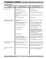
Page 13: ... 7 Periodic Maintenance Check for leakage Pump damaged or worn Repair or replace pump Internal leakage Remove reservoir inspect pump outlet fitting and hose connections for tightness inspect O ring seal on outlet fitting repair or replace com ponents as necessary External leakage Locate leakage point Tighten replace or repair components as necessary Engine output insufficient Adjust throttle tune ...

Page 14: ...d be removed and cleaned whenever reservoir is removed Loosen nut of male connector 9 and turn tube 27 aside Remove baffle 30 Note Do not adjust the hex nuts and washers located on studs 29 2 Remove swivel nut of hose assembly 32 from elbow 33 leaving elbow in place Remove hex head cap screws 19 and washers from pump flanges Spacers 18 may fall free Loosen set screw 16 which secures the pump shaft...

Page 15: ...al ring 4 into groove 7 Install dowel pins 7 into body 13 Lubricate bushings in cover with SAE 10 oil and install cover 10 matching scribe marks on cover and body 8 Insert cap screws 1 and washers 2 Torque to 7 8 foot pounds Install Woodruff key 9 Turn drive shaft with adjustable wrench to ensure that no mechanical binding occurs 9 See Exploded View HG3505 Power Unit Install pump shaft into couple...

Page 16: ...tron Inc 16 4455 Boeing Dr Rockford IL 61109 2988 815 397 7070 HG3505A 42303 Portable Power Unit HG3505A Power Unit 24 23 22 10 13 26 9 15 36 31 12 11 14 27 5 29 19 8 7 6 1 9 30 37 34 38 42 39 40 24 28 32 33 17 21 20 9 16 18 41 25 3 4 5 ...

Page 17: ...1 18 44113 134329 Spacer 2 19 44114 F022613 Cap Screw Hex Head 5 16 24 x 5 Zinc Plated 2 20 41973 F022614 FILTER 1 21 41397 F012813 O Ring 644 x 818 x 087 90 1 22 41974 F022615 Breather Filler Plug 1 23 41975 F022616 Bypass Valve 1 43318 43318 Replacement Seal Kit 1 24 44115 F022617 Elbow 90 3 8 MNPT x 3 8 FNPT 2 25 41692 F018353 Level Seal Plug 1 4 NPTF 1 26 41976 F022618 Relief Valve 1400 PSI 1 ...

Page 18: ...4 2 48545 Flat Washer 4 3 48546 Pipe Plug 1 4 48547 Seal Ring 1 5 48548 Wear Plate 1 6 48549 Pressure Loading Seal 1 7 48550 Dowel Pin 2 8 48551 Shaft Seal 1 9 48552 Woodruff Key 1 10 48553 Cover 1 11 48554 Driven Gear 1 12 48555 Drive Gear 1 13 48556 Body Assembly 1 14 48557 Pressure Loading Seal Nylatron 1 Identifies items included in Seal Kit 43293 1 2 10 4 12 9 7 14 6 5 3 LARGE PORT IN DETAIL ...

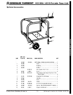
Page 19: ...0899 135586 OPTIONAL WHEELS AND HANDLE 1 1 48558 Axle 1 2 48559 Washer 4 3 48560 Wheel 2 4 F003141 Pin Cutter 1 8 x 1 1 2 2 5 48561 48561 Foot 2 6 41256 F001213 Cap Screw Hex Head 1 4 20 x 1 1 4 Zinc Plated 2 7 41431 F013588 Stop Nut 1 4 20 Helas 2 8 48562 Handle 1 9 48563 Grip 1 10 40875 134719 Chain 1 11 41994 F022696 Pin 5 16 Quick Disconnect 1 12 40892 135328 Decal CAUTION DO NOT TOUCH 1 13 49...

Page 20: ...ust be taken to protect the hose from excessive abrasion which can result in erosion snagging and cutting of the hose cover Exposure of the reinforcement will significantly accelerate hose failure 2 10 Proper End Fitting Care must be taken to insure proper compatibility exists between the hose and coupling selected based on the manufacturer s recom mendations substantiated by testing to industry s...

Page 21: ... all air entrapment must be eliminated and the system pressurized to the maximum system pressure and checked for proper function and freedom from leaks Note Avoid potential hazardous area while testing 4 MAINTENANCE Even with proper selection and installation hose life may be significantly reduced without a continuing maintenance program Frequency should be determined by the severity of the applic...

Page 22: ...xtron Inc 4455 Boeing Drive Rockford IL 61109 2988 USA Customer Service International 815 397 7070 Fax 815 397 1391 Customer Service North America 800 435 0786 Fax 800 451 2632 815 397 1865 Canada Fax 800 524 2853 Printed in the U S A ...

Reviews: