background image

Greenlee / A Textron Company

7

4455 Boeing Dr. • Rockford, IL 61109-2988 USA • 815-397-7070

CK1240 and CK1240C Crimping Tools

Operation

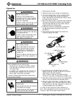
1. Clean the die seat area.

2. Install the proper size and type of crimping dies.

3. Press the release button on the C-head and slide

one of the die halves into the jaw. Release the
button and slide the die half until the retainer snaps
and locks the die into place.

4. Press the release button on the ram body (located in

the cutout) and slide the other die half in. Release
the button and slide the die half until the retainer
snaps and locks the die into place.

5. Follow the connector manufacturer’s instructions

for appropriate cable strip length and surface
preparation.

6. Insert cable fully into connector and center the

connector between the dies.

CRIMPING DIRECTION

1ST COMPRESSION

CRIMPING DIRECTION

SIDE A

CRIMPING DIRECTION

SIDE B

1ST COMPRESSION

SIDE A

1ST COMPRESSION

SIDE B

7. Using the sequence illustrated here, press the

trigger to advance the dies. Continue to crimp until
the pressure relief valve activates.
Note: Pressure relief occurs at approximately
106 kN (12 tons) and is indicated by an audible “pop.”

8. After achieving pressure relief, the ram automatically

returns to the start position and the dies retract.

9. When using KC12-type dies, complete the number

of crimps listed on the “Connector Selection” chart in
this manual. For other dies, complete the number of
crimps specified by the manufacturer.

10. Remove the connector from the crimping tool.
Note: After completing the last crimp on an aluminum
connector, wipe off the excess oxide inhibitor.

Pinch points:

Keep hands away from the crimping
tool head when crimping.

Failure to observe this warning could
result in severe injury or death.

Electric shock hazard:

This tool is not insulated. When
using this unit on or near energized
electrical lines, use proper personal
protective equipment.

Failure to observe this warning could
result in severe injury or death.

Wear eye protection when operating
or servicing this tool.

Failure to wear eye protection could
result in serious eye injury from
flying debris or hydraulic oil.

Skin injection hazard:

Do not use hands to check for oil
leaks. Oil under pressure easily
punctures skin. If injured, seek
medical attention immediately to
remove oil.

Failure to observe this warning could
result in serious injury, gangrene, or
death.

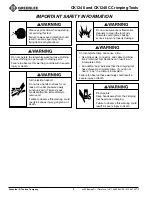
An incomplete crimp can cause a fire.

• Use proper die, connector, and cable combina-

tions. Improper combinations can result in an
incomplete crimp.

• An audible “pop” indicates that the crimping tool

has achieved a complete crimp. If you do not
hear a “pop,” the crimp is incomplete.

Failure to observe these warnings could result in
severe injury or death.

Summary of Contents for GATOR CK1240

Page 1: ...reenlee Textron Inc IM 1508 REV 2 5 04 Read and understand all of the instructions and safety information in this manual before operating or servicing this tool GATOR CK1240 and CK1240C Crimping Tools...

Page 2: ...Relief Valve Check 9 Troubleshooting 10 Disassembly 11 Assembly 12 Illustrations and Parts List 13 18 Description The CK1240 Hydraulic Crimping Tool is a hand held self contained tool intended to cri...

Page 3: ...the plug not the cord Disconnect from power before servicing Failure to observe these warnings could result in severe injury or death Do not use this crimping tool in a hazardous environment Hazards i...

Page 4: ...ught in moving parts Failure to observe this warning could result in severe injury or death Wear eye protection when operating or servicing this tool Failure to wear eye protection could result in ser...

Page 5: ...evere injury or death Do not operate the tool without dies Damage to the ram or crimping tool head can result This tool is not designed for continuous use After 30 to 40 crimping cycles allow the crim...

Page 6: ...Tool Length 396 mm 15 6 Width 80 mm 3 16 Height 279 mm 11 Mass Weight 6 3 kg 13 9 lb Sound Level 75 dB A at 1 meter Vibration 2 5 m s2 Motor Voltage CK124011 and CK1240C11 120 VAC 60 Hz 2 1 A CK12402...

Page 7: ...9 When using KC12 type dies complete the number of crimps listed on the Connector Selection chart in this manual For other dies complete the number of crimps specified by the manufacturer 10 Remove th...

Page 8: ...YA 2N YA 2TC CRA 2L CRB 2L LCB LCC 54850BE 54880BE BBLU YAZ 2N YAZ 2TC CRC 2L Catalog UPC Cable Color No of Number Number Size Code Crimps KC12 8 10996 8 AWG Red 1 KC12 6 10997 6 AWG Blue 1 KC12 4 109...

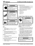
Page 9: ...vel 1 Remove the two screws that retain the tank housing cover Remove the tank housing cover 2 Point the crimping head downward and remove the oil reservoir plug Fill reservoir if necessary 3 Replace...

Page 10: ...ed Return tool to an authorized Greenlee service center Dies stop during operation Oil level is low Check oil level Refill reservoir Air in hydraulic system Pull trigger and hold retract button simult...

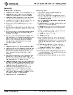
Page 11: ...80 Gently tug it over the reservoir 2 Remove the reservoir 74 3 Remove the pump piston 152 4 Remove the screw plug 151 washer 153 pump piston 150 valve stem 156 and spring 155 Replace the sealing was...

Page 12: ...the release lever 107 so that the forked end engages the unloading valve subassembly between the pressure relief 126 and the support ring 127 Install the screw 99 and washer 104 5 Insert the threaded...

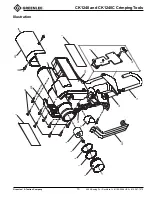
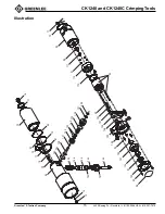
Page 13: ...Greenlee A Textron Company 13 4455 Boeing Dr Rockford IL 61109 2988 USA 815 397 7070 CK1240 and CK1240C Crimping Tools Illustration 5 4 6 7 8 2 52 50B 52 50C 3 1 50A 50D 51 56 55 10 9 54...

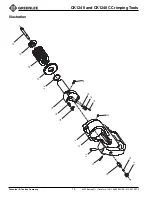
Page 14: ...Greenlee A Textron Company 14 4455 Boeing Dr Rockford IL 61109 2988 USA 815 397 7070 CK1240 and CK1240C Crimping Tools Illustration 22 23 27 24 25 3 36 35 34 38 37 21 39 41 40 30 31 33 32 26...

Page 15: ...88 USA 815 397 7070 CK1240 and CK1240C Crimping Tools Illustration 72 73 83 79 81 70 80 71 76 74 82 75 77 78 155 156 150 153 152 151 154 128 129 122 123 124 120 121 130 125 126 127 96 92 91 101 93 102...

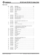
Page 16: ...1582 6 Capacitor 3 12 500 1581 8 Cable tie 1 13 500 1583 4 Tap 4 8 x 0 5 not shown 1 500 5373 6 C head assembly 42 mm includes items 3 21A and 22 27 500 7217 0 C head assembly 42 mm PVC covered includ...

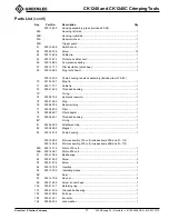
Page 17: ...4144 4 Threaded bushing 1 73 O ring 1 74 500 5873 8 Hydraulic reservoir 1 75 500 4198 3 Ring 1 76 500 5878 9 Reservoir plug 1 77 500 5880 0 Filter 1 78 500 5882 7 Filter adapter 1 79 500 5885 1 Thread...

Page 18: ...871 1 Adjusting nut 1 127 500 5875 4 Support ring 1 128 Retaining ring 1 129 500 5877 0 Needle valve 1 130 500 5894 0 Spring 1 500 1348 3 Piston pump assembly includes items 150 156 150 500 5891 6 Pum...

Reviews: