CSG45GL Cable Cutter
Greenlee Textron / Subsidiary of Textron Inc.
15
4455 Boeing Dr. • Rockford, IL 61109-2988 USA • 815/397-7070
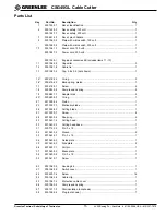
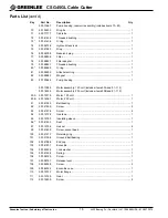
Parts List
Key
Part No.
Description
Qty
1
500 1539.7
Decal, identification ........................................................................... 1
2
500 1425.0
Decal, safety, 120 volt ....................................................................... 1
500 1527.3
Decal, safety, 230 volt ....................................................................... 1
3
500 6214.0
Decal, pinch hazard ........................................................................... 2
9
500 1560.5
Plate with microswitch, 120 volt ........................................................ 1
500 1689.0
Plate with microswitch, 230 volt ........................................................ 1
10
500 1561.3
Power cord, 120 volt .......................................................................... 1
500 1627.0
Power cord, 230 volt .......................................................................... 1
500 1559.1
Engine accessories kit (includes items 11–13)
11
500 1582.6
Capacitor ........................................................................................... 3
12
500 1581.8
Cable tie ............................................................................................ 1
13
500 1583.4
Tap, 4.8 x 0.5 (not shown) ................................................................. 1
15*
500 4192.4
O-ring ................................................................................................ 3
16*
500 4194.0
Backup ring, piston ............................................................................ 1
17
500 4168.1
Screw ................................................................................................ 2
18
500 5825.8
Compression spring .......................................................................... 2
19
500 5837.1
Adapter disk ...................................................................................... 2
20*
500 5838.0
O-ring ................................................................................................ 1
21
501 0396.2
Piston ................................................................................................ 1
25
501 0397.0
Stationary blade ................................................................................ 1
26
501 0398.9
Cutting blade ..................................................................................... 1
27
501 0399.7
Screw ................................................................................................ 4
28
501 0400.4
Snap ring ........................................................................................... 2
29
501 0401.2
Cutting head ...................................................................................... 1
30
501 0402.0
Cutting head base ............................................................................. 1
31
500 7122.0
Pin, 3 x 18 ......................................................................................... 1
32
501 0403.9
Sleeve ............................................................................................... 2
33
501 0404.7
Pin, 3 x 18 ......................................................................................... 1
34
501 0405.5
Guide plate ........................................................................................ 1
35
501 0406.3
Side plate .......................................................................................... 2
36
501 0407.1
Pull pin ............................................................................................... 1
37
501 0408.0
Brace plate ........................................................................................ 1
38
501 0409.8
Pin, 3 x 18 ......................................................................................... 1
39
501 0410.1
Screw ................................................................................................ 1
50
500 1563.0
Housing kit ......................................................................................... 1
51
500 1564.8
Switch cover ...................................................................................... 1
52
500 4207.6
Screw .............................................................................................. 14
54
500 1565.6
Cable clip ........................................................................................... 1
55
500 1567.2
Protective cable cover ....................................................................... 1
56
500 1569.9
Compression spring .......................................................................... 1
57
500 1571.0
Film insulation (not shown) ................................................................ 1
58
500 1566.4
Plug (not shown) ............................................................................... 1

