background image

Greenlee Textron / Subsidiary of Textron Inc.

12

4455 Boeing Dr., Rockford, IL 61109-2988   815/397-7070

GATOR

TM

 ES1000 Battery-Powered Cutter

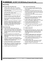
Reassembly

Motor/Gearbox/Bearing Reassembly

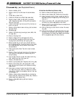
1.

Install two fillister head screws (27) into spacer
(not numbered) and motor (24). Tighten screws.

2.

Install four screws (not numbered) into gear housing
(28). Tighten screws.

3.

Install four screws (29) into mounting block (8) and
gear housing (28). Tighten screws.

4.

Replace grooved ball bearing (31) and snap ring
(30) subassembly.

5.

Replace eccentric (51). Use a fiber mallet to tap
eccentric onto shaft. Replace ball bearing (50).

6.

Align end cap (53). Use a fiber mallet to tap cover
until it is flush on mounting block (8). Install two
screws (54).

7.

Align gear housing/motor subassembly so that the
pump piston (49) extends through the mounting
block (8) and makes contact with the grooved
bearing (31). Locate and start the three screws (7)
through the mounting block and into the pump
housing. Tighten the screws.

Pump Subassembly

8.

Insert pump piston (49) into pump housing.

9.

Insert seal (4) and unloading valve assembly into
pump housing. Grasp needle valve subassembly by
the pressure relief (11) and twist it several turns
clockwise. Stop when the mark or piece of tape is
facing up.

10. Assemble pump piston (45), valve stem (44),

spring (43) and screw plug (41). Be sure to replace
sealing washer (45). Torque screw plug (41) to 75
foot-pounds.

11. Install release lever (19) so that the forked end

engages the unloading valve subassembly between
the pressure relief (11) and the support ring (12).
Install screw (15) and washer (57).

12. Insert threaded bushing (37) and feed tube sub-

assembly (34, 35 and 36). Screw in until snug.

13. Install reservoir (17). Slip the O-ring (38) over the

reservoir. Using a hooked tool, carefully slip the
O-ring over the lip of the pump housing.

14. Insert the plug (16) into the reservoir.

Misc. Components Reassembly

15. Remove the protective plastic bag from the elec-

tronics subassembly. Insert the LED into the LED
bushing (221).

16. Lay the gear housing/motor subassembly into the

right half of the housing. Insert the circuit board into
the circuit board slot, so that the wires and chip face
in the direction of the trigger.

17. Lay the wires into case. Be sure that the wires will

not be pinched.

18. Guide the wires for the battery clip so that battery

wires lay on top of the electronics box; install the
battery clip so the red wire is upward.

19. Install the trigger (213) and trigger lock (214).

Depress and release the trigger and slide the trigger
lock to be sure that they operate freely.

20. Locate the right housing half on top of the left

housing half. Check for pinched wires.

21. Install the housing screws (208, 209, 210 and 216).

Note: Handle screw (216) must engage the nut

(217).

22. Install the piston (203).

23. Install the spring (201).

24. Replace the front head assembly. Twist the cutting

head base (120) until it stops; back off 3/4 of a turn
and tighten the screws (121). Be sure that the
crimping head assembly rotates freely approxi-
mately 350

°

.

25. Install the moveable blade (101). Insert the screw

(119) through the blade and piston and tighten.

26. Clamp the head assembly into a vise with the

reservoir plug facing upward. Remove the fill plug
(16) and fill the reservoir with hydraulic oil.

27. Install the battery (230).

28. Squeeze the trigger while depressing the release

lever for 45-60 seconds. Fill the reservoir with
hydraulic oil. Replace the fill plug (16).

29. Replace the tank cover (218) and tank cover screws

(219).

Summary of Contents for GATOR ES1000

Page 1: ...3024 2 2000 Greenlee Textron IM 1364 REV 1 2 00 GATORTM ES1000 BATTERY POWERED CUTTER 1 7 Ah 12V 12V Read and understand all of the instructions and safety information in this manual before operating...

Page 2: ...up to 1 1 2 40 mm diameter Standard Guy strand up to 3 4 20 mm diameter not EHS Ground rod up to 5 8 16 mm diameter Wire rope up to 5 8 16 mm diameter Rebar reinforcing Bar up to 1 2 13 mm diameter P...

Page 3: ...able under tension Cable will fall and may strike nearby personnel Failure to observe this warning can result in severe injury or death IMPORTANT SAFETY INFORMATION This symbol is used to call your at...

Page 4: ...s allow the tool to cool for 15 minutes Do not secure this tool in a vise A vise can damage the housing Do not use this tool in rain or wet conditions Any moisture inside the housing can damage intern...

Page 5: ...TM ES1000 Battery Powered Cutter Identification 1 Trigger 2 Retract Button 3 Locking Flange 4 Cutting Head 5 Housing 6 Battery Load Display 7 Battery 8 Trigger Lock 9 Hand Guard 10 Moveable Cutting Bl...

Page 6: ...lbs 5 6 kg Sound Level 75 dB A at 1 meter Vibration 2 5 m s2 Motor Voltage 12 VDC Hydraulic Oil 0 1 pint 50 ml Shell Tallus T 15 Cutting Capacities Cutting Force 60 kN 6 7 tons Cuts per Charge approxi...

Page 7: ...use this tool for continuous use After 30 40 cutting cycles allow the tool to cool for 15 minutes Do not secure this tool in a vise A vise can damage the housing Do not use this tool in rain or wet c...

Page 8: ...ttery load display to light at both the beginning of a cutting cycle and at the point of maximum pressure Cutting Cable 1 Open the head by lifting the locking flange 2 Position the cable in the open c...

Page 9: ...towards the ground and remove the oil plug Refill reservoir if necessary 4 Replace the oil plug and the tank housing cover Recommended Hydraulic Oils AVIA HVI 15 Shell Tellus T 15 MOBIL DTE 11 NUTO H...

Page 10: ...Check oil level Fill reservoir if is complete necessary Air in hydraulic system Pull trigger and hold release lever simultaneously Hold for approximately 10 seconds Exceeded capacity of cutter Use al...

Page 11: ...g motor subassembly from pump housing 16 Use a hooked tool to remove the reservoir O ring 38 Gently tug it over the reservoir 17 Remove the reservoir 17 18 Remove pump piston 49 Replace the O ring 48...

Page 12: ...36 Screw in until snug 13 Install reservoir 17 Slip the O ring 38 over the reservoir Using a hooked tool carefully slip the O ring over the lip of the pump housing 14 Insert the plug 16 into the rese...

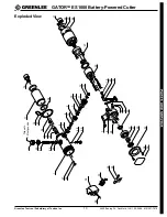
Page 13: ...rd IL 61109 2988 815 397 7070 GATORTM ES1000 Battery Powered Cutter Exploded View 39 40 38 34 35 37 6 1 47 46 48 49 16 4 5 32 25 26 33 44 45 41 42 43 58 17 38 29 52 54 53 50 51 31 19 7 30 57 18 15 28...

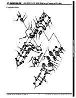
Page 14: ...ary of Textron Inc 14 4455 Boeing Dr Rockford IL 61109 2988 815 397 7070 GATORTM ES1000 Battery Powered Cutter Exploded View 218 219 211 226 221 217 230 231 215 228 216 219 208 225 209 210 206 207 203...

Page 15: ...4455 Boeing Dr Rockford IL 61109 2988 815 397 7070 GATORTM ES1000 Battery Powered Cutter Exploded View 123 122 120 121 102 114 111 106 113 117 115 119 121 110 102 107 109 112 100 116 108 105 104 103 1...

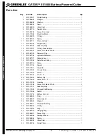
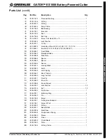
Page 16: ...g 1 17 500 5873 8 Hydraulic Reservoir 1 18 500 5879 7 Release Lever 1 19 500 4125 8 Relief Lever Spring 1 20 500 5872 0 Screw 1 21 500 4113 4 Spacer 1 22 500 4137 1 Capacitor 3 23 500 4136 3 Ground St...

Page 17: ...le Blade 1 102 500 5985 8 Side Plate 2 103 500 5986 6 Spacer 2 104 500 5988 2 Spacer 1 105 500 5990 4 Spacer 1 106 500 5991 2 Locking Block 1 107 500 5992 0 Latch 1 108 500 5993 9 Latch Spring 1 109 5...

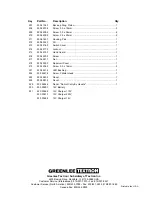
Page 18: ...500 4209 2 Screw 3 9 x 25mm 2 211 500 6742 7 Housing Pair 1 212 500 6334 0 Oil 1 213 500 4216 5 Switch Cover 1 214 500 4217 3 Lockout 1 215 500 4219 0 Hand Guard 1 216 500 4220 3 Screw 1 217 500 4221...

Reviews: