Greenlee Textron / Subsidiary of Textron Inc.
14
4455 Boeing Dr., Rockford, IL 61109-2988 815/397-7070
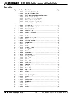
ESG45GL Battery-powered Cable Cutter
501 0394.6
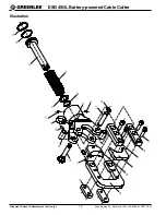
Head and Ram Unit (15–39)
500 1345.9
Housing Unit, green (50–61)
500 1346.7
Pump Housing, Reservoir Assembly (70–83)
500 1349.1
Motor Assembly (90–112)
500 5903.3
Relief Valve Assembly (120–130)
500 1347.5
Electrical Assembly (140–144)
500 1348.3
Piston Pump Assembly (150–156)
8
500 6334.0
Oil (not shown) .................................................................................. 1
9
500 7176.9
Circuit Board Programmed ................................................................ 1
10
501 0308.6
Decal, Identification ........................................................................... 1
11
501 0309.4
Decal, Warning .................................................................................. 1
12
500 6214.0
Decal, Pinch Hazard .......................................................................... 1
15
500 4192.4
O-ring ................................................................................................ 3
16
500 4194.0
Back-up Ring, Piston ......................................................................... 1
17
500 4168.1
Screw ................................................................................................ 2
18
500 5825.8
Compression Spring .......................................................................... 2
19
500 5837.1
Adapter Disk ...................................................................................... 2
20
500 5838.0
O-ring ................................................................................................ 1
21
501 0396.2
Piston ................................................................................................ 1
25
501 0397.0
Stationary Blade ................................................................................ 1
26
501 0398.9
Cutting Blade ..................................................................................... 1
27
501 0399.7
Screw ................................................................................................ 4
28
501 0400.4
Snap Ring .......................................................................................... 2
29
501 0401.2
Cutting Head ..................................................................................... 1
30
501 0402.0
Cutting Head Base ............................................................................ 1
31
500 7122.0
Pin, 3 x 18 ......................................................................................... 1
32
501 0403.9
Sleeve ............................................................................................... 2
33
501 0404.7
Pin, 3 x 18 ......................................................................................... 1
34
501 0405.5
Guide Plate ........................................................................................ 1
35
501 0406.3
Side Plate .......................................................................................... 2
36
501 0407.1
Pull Pin .............................................................................................. 1
37
501 0408.0
Brace Plate ........................................................................................ 1
38
501 0409.8
Pin, 3 x 18 ......................................................................................... 1
39
501 0410.1
Screw ................................................................................................ 1
50
500 7142.4
Housing Unit, green ........................................................................... 1
51
500 4220.3
Screw ................................................................................................ 1
52
500 4221.1
Nut ..................................................................................................... 1
53
500 7373.7
Switch Cover ..................................................................................... 1
54
500 4128.2
Battery Clip ........................................................................................ 1
55
500 4236.0
Screw ................................................................................................ 2
56
500 4207.6
Screw ................................................................................................ 4
57
500 4209.2
Screw ................................................................................................ 2
Parts List
Key
Part No.
Description
Qty

