HPB25 Hydraulic Paving Breaker
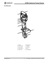
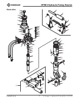
Parts List
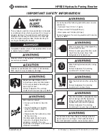
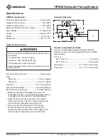
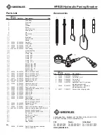
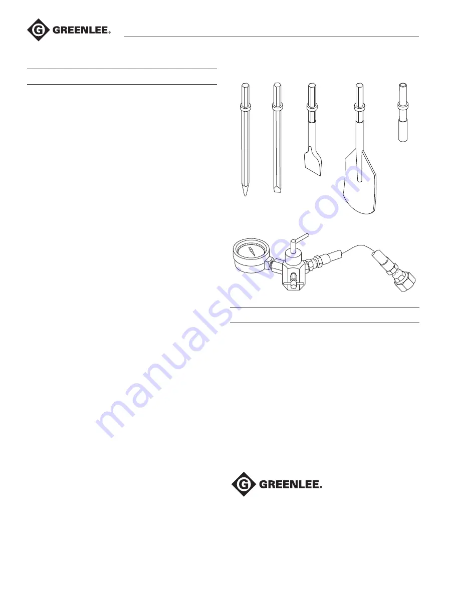
Accessories
6
1
3
4
5
2
UPC No.
Key 78-3310- Part No.
Description
1
41610
50416103 Moil point
2
46260
50462601 Chisel bit, 1-3/8"
3
46253
50462539 Chisel bit, 3"
4
46289
50462890 Clay spade
5
41070
50410703 Rod driver (for 5/8" maximum
diameter ground rod)
46223
50462237 Rod driver (for 1" maximum
diameter ground rod)
6
46251
50462512 Accumulator charging valve
UPC No.
Key 78-3310- Part No.
Description
Qty
1
Valve body ............................................1
2
Front end...............................................1
3
Shell ......................................................1
4
Cylinder .................................................1
5
Piston ....................................................1
6
Chisel bushing ......................................1
7
Valve guide ............................................1
8
Lid .........................................................1
9
Inner tube ..............................................1
10
Cap .......................................................1
11*
Steel ball ...............................................1
12
Control valve .........................................1
13*
Spring ...................................................1
14
45954
50459546 Cap bolt ................................................1
15 45955 50459554 Diaphragm ............................................1
16
45956
50459562 Valve rod ...............................................1
17
45957
50459570 Latch (1") ...............................................1
18 45958G 50459589 Lock spring ...........................................1
19*
U-cup packing ......................................1
20*
Dust seal ...............................................1
21*
O-ring, G60 ...........................................1
22*
O-ring, S70 ...........................................1
23*
O-ring, P22 ...........................................1
24*
O-ring, P5 .............................................1
25*
O-ring, P14 ...........................................1
26*
O-ring, P12.5 ........................................1
27*
Backup ring, G60 ..................................1
28*
Backup ring, P22 ..................................1
29*
Backup ring, P14 ..................................1
30*
Backup ring, P5 ....................................1
32*
Seal washer ..........................................1
33
45973
50459732 Bolt, hex socket, 8x80 ..........................4
34
45974
50459740 Bolt, hex socket, 8x15 ..........................4
35
45975
50459759 Bolt, hex socket, 10x50 ........................1
36
45976
50459767 Spring pin, Ø16x50 ...............................1
37
45977
50459775 Spring pin, Ø10x50 ...............................1
38 45978G 50459783 Spring pin, Ø6x20 .................................1
39
45979
50459791 Needle roller ..........................................1
40
52183
52049243 Hydraulic hose set ................................1
42
50017462 Decal, identification ..............................1
44
49009
50490095 Decal, warning ......................................1
46
45983
50459830 Taper plug, hex socket, PT1/8 ............10
47
45984
50459848 Handle grip ...........................................1
48
45985
50459856 Handle stay ...........................................1
49
45986
50459864 Handle stay ...........................................1
50
45987
50459872 Push rod ...............................................1
51
45988
50459880 Control lever..........................................1
52
45989
50459899 Handle pipe ...........................................1
53
Bolt, hex socket, M6x15 .......................4
54
Bolt, hex socket, M8x15 .......................2
55
45992
50459929 Spring pin, Ø5x22 .................................1
56
46197
50461974 Decal, caution .......................................1
57
45898
50458981 Decal, pressure/flow/weight .................1
58 46258G 50462580 Handle, side (includes items 59–66)
59
Bracket, handle, top half .......................1
60
Bracket, handle, bottom half ................1
61
Pin, center .............................................1
62
Bolt, 8 mm x 35 mm .............................2
63
Washer, handle .....................................3
64
Bolt, handle ...........................................1
65
Pin, bracket ...........................................1
66
Grip, handle ..........................................1
Kits
*
46296
50462962 Seal kit (includes items marked
with an asterisk)
4455 Boeing Drive • Rockford, IL 61109-2988 • USA • 815-397-7070
An ISO 9001 Company • ©2019 Greenlee Tools, Inc.
USA
Tel: 800-435-0786
Fax: 800-451-2632
Canada
Tel: 800-435-0786
Fax: 800-524-2853
International
Tel: +1-815-397-7070
Fax: +1-815-397-9247
www.greenlee.com