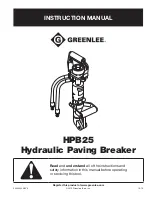
HPB25 Hydraulic Paving Breaker
Greenlee Tools, Inc.
4455 Boeing Dr. • Rockford, IL 61109-2988 USA • 815-397-7070
9
Maintenance
Use this maintenance schedule to maximize the tool’s
service life.
Note: Keep all decals clean and legible. Replace decals
when necessary.
Daily
1. Wipe all tool surfaces clean.
2. Inspect the hydraulic hoses and fittings for signs
of leaks, cracks, wear or damage. Replace if
necessary.
3. Install dust caps over the hydraulic ports when the
tool is disconnected.
Monthly
Perform a thorough inspection of the hydraulic hoses
and fittings as described in publication 99930323,
SAE J1273 (Hose and Hose Assemblies).
Annually
If required by your organization, have the tool inspected
by a Greenlee Authorized Service Center.
Accumulator Recharging Procedure
If the tool strike rate is normal, however the blow energy
appears weak, the accumulator nitrogen pressure may
be low. Check the nitrogen pressure according to the
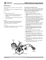
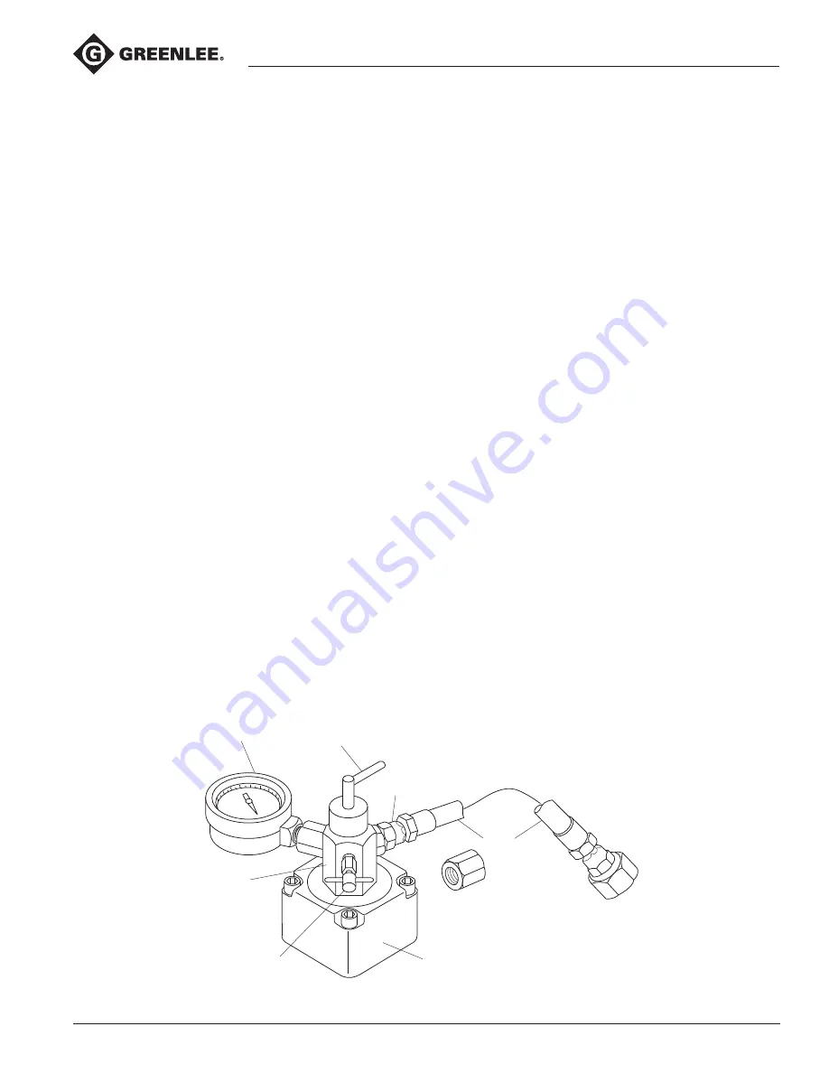
following procedure. Refer to figure below.
1. Remove the accumulator cap.
2. Attach the charging valve (Accessory P/N
50462512) to the accumulator surface and hand-
tighten.
3. Cap the hose connection port of the charging valve.
Close the relief valve on the charging valve.
4. Slowly turn the handle counterclockwise to open the
accumulator valve until pressure is read on the pres-
sure gauge. If the pressure gauge reads less than 32
kg/cm
2
(455 psi), then the pressure needs
to be increased to 40 kg/cm
2
(569 psi).
5. If the pressure needs to be adjusted, turn the handle
clockwise to close the accumulator valve. Open
the relief valve to remove nitrogen from within the
charging valve.
6. Remove the cap from the hose connection port
and attach the supply hose from the nitrogen
gas cylinder whose available pressure is at least
45 kg/cm
2
(640 psi).
7. Close the relief valve by turning it clockwise.
8. Open the nitrogen supply tank to provide 40 kg/cm
2
(569 psi) pressure.
9. Slowly turn the handle on top of charging valve
counterclockwise to open the accumulator valve.
10. Once pressure has stabilized, turn the handle on top
of the charging valve clockwise to close the accu-
mulator valve.
11. Close the valve to the nitrogen gas cylinder. Open
the relief valve to remove the pressure from within
the charging valve.
12. Remove the charging valve from the accumulator
and reinstall the accumulator cap.
Charging
valve
Pressure
gauge
Handle
Nut
Relief valve
Accumulator
Gas cylinder
Hose
Cap

