background image

Greenlee Textron / Subsidiary of Textron Inc.

6

4455 Boeing Dr., Rockford, IL 61109-2988   815/397-7070

7904SB/7906SB Hydraulic Punch Driver

123456

123456

123456

123456

123456

1234

1234

1234

1234

123456789012345

123456789012345

123456789012345

123456789012345

12345678901

12345678901

12345678901

12345678901

12345678901

12345678901

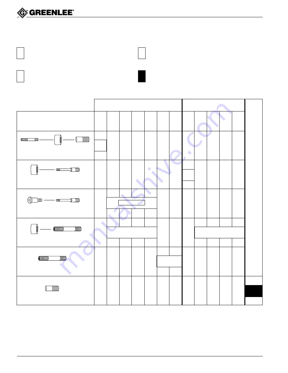
Capacity and Draw Stud Selection Guide

1614SS

DRAW STUD

1924AA

SPACER

33967

ADAPTER

1924AA

SPACER

29451

7/16" DRAW STUD

29451

7/16" DRAW STUD

31874

ADAPTER

1924AA

SPACER

31872

3/4" DRAW STUD

31872

3/4" DRAW STUD

33967

ADAPTER

Stud and Accessories

1/2"

con.

ø 0.885"

15.2 mm

3/4"

con.

ø 1.115"

28.3 mm

1-7/32"

1"

con.

ø 1.362"

34.6 mm

1-1/4"

con.

ø 1.701"

43.2 mm

1-1/2"

con.

ø 1.951"

49.6 mm

2"

con.

ø 2.416"

61.5 mm

1/2"

con.

ø 0.885"

15.2 mm

3/4"

con.

ø 1.115"

28.3 mm

1-7/32"

1"

con.

ø 1.362"

34.6 mm

1-1/4"

con.

ø 1.701"

43.2 mm

Electronic Connector Punches

RS-232, 229, 231, 234, 238.

Standard & Slug-Buster

®

 Punches

Slug-Splitters

®

12345678901234567890123456789

12345678901234567890123456789

12345678901234567890123456789

12345678901234567890123456789

12345678901234567890123456789

12345678901234567890123456789

12345678901234567890123456789

12345678901234567890123456789

1234567890123456789012

1234567890123456789012

1234567890123456789012

1234567890123456789012

1234567890123456789012

See Note 

See Note 

The Slug-Buster

®

 punches may not split the slug when used with this adapter, because of the smaller pilot hole.

The 31874 step-saver adapter and 29451 draw stud are included with the 7804SB only.
They may be purchased separately and used with any Quick-Draw™ hydraulic punch driver kit.

See Note 

12345

12345

12345

12345

12345

12345

12345

12345

123

123

123

123

123

1234

1234

1234

1234

1234

14 Ga. (0.0747" [1.9 mm])
Mild Steel

10 Ga. (0.1345" [3.4 mm])
Mild Steel

10 Ga. (0.1345" [3.4 mm])
Stainless Steel

16 Ga. (0.0598" [1.5 mm])
Mild Steel & 1/18" Soft Aluminum

www.

GlobalTestSupply

.com

Find Quality Products Online at:

sales@GlobalTestSupply.com

Summary of Contents for Quick Draw 90 7904SB

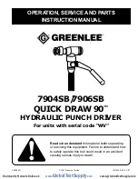
Page 1: ...YDRAULIC PUNCH DRIVER For units with serial code WV Read and understand this material before operating or servicing this equipment Failure to understand how to safely operate this tool could result in...

Page 2: ...uds form a complete system for punching holes of various shapes and sizes through mild steel aluminum fiberglass and plastic Slug Splitter punches dies and studs are available for punching all of thes...

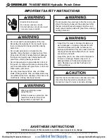
Page 3: ...ttention to instructions concerning your personal safety Watch for this symbol It points out important safety precautions It means Read the message that follows and be alert to the possibility of pers...

Page 4: ...nd draw stud with great force and could strike nearby personnel Use only Greenlee punches dies and draw studs Other punches dies and draw studs may not withstand the force capacity of the driver and c...

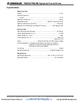
Page 5: ...rating Pressure 10 000 lbs Volume Operating Total Cu In 2 0735 Volume Stroke Cu In In 0525 Circuit Capacity Cu In Total 3 50 Reservoir 2 32 Seals Nitrile Fluorocarbon Teflon Back up Rings Fluid Compat...

Page 6: ...31 234 238 Standard Slug Buster Punches Slug Splitters 12345678901234567890123456789 12345678901234567890123456789 12345678901234567890123456789 12345678901234567890123456789 1234567890123456789012345...

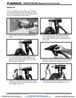
Page 7: ...le and repeat steps 4 and 5 The 1 2 conduit size punch is often used to increase the size of the pilot hole this is called step up punch ing After enlarging the pilot hole the 3 4 draw stud is used to...

Page 8: ...eed for step up punching Note The stud and adapter are rated to drive the 1 1 4 punch through 14 gauge mild steel Do not exceed the rated capacity of the 29451 draw stud and 31874 step saver adapter E...

Page 9: ...optional 31874 step saver adapter cont d 7 Turn release valve knob clockwise Pump lever handle until the punch is completely through the material 8 Release by turning the release valve knob counter c...

Page 10: ...of oil leaks must build oil pressure and the ram section right angle head must rotate by hand force Oil Leaks Check for external oil leaks Check that release valve knob and stem are closed tightly an...

Page 11: ...ly Ram Section 1 Lightly coat ram 3 and cylinder 1 seals and both bores of the cylinder with clean oil 2 Push ram completely into cylinder 3 Thread installation rod into tapped hole in the ram and ins...

Page 12: ...tion check for lubrication or damage at threads closest to set screw 13 also check adjustment of set screw 13 Reassembly Pump Section Fill plunger 24 bore with clean hydraulic oil Coat O ring seals on...

Page 13: ...Chart Material being punched is too thick or too hard See Capacity Chart Pump will not build pressure Air in system See step 3 Adding Hydraulic Oil Excessive number of strokes Inoperative intake check...

Page 14: ...vel Inspection excess oil in unit External oil leaks Damaged seals or surfaces Damaged piston piston extension pump plunger seals or mating surfaces See Troubleshooting and Repair Cylinder and Pump Bl...

Page 15: ...28 27 16 6 6 12 2 39 33 36 31 32 40 24 37 30 37 37 30 37 37 23 43 13 26 5 41 15 14 8 11 1 9 3 10 7 4 17 12 Repair Kits 503 4296 7 Release Valve Unit Repair Kit includes items keyed in black circles 16...

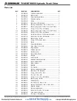
Page 16: ...03 4301 7 Decal identification 1 19 502 3258 4 Grip 600 x 1 00 x 4 50 1 20 503 2488 8 Plug bladder 1 21 503 4281 9 Handle reservoir 1 22 503 4285 1 Handle pump 1 23 503 4275 4 Seat intake check 1 24 5...

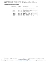
Page 17: ...SCRIPTION QTY 29451 502 9451 2 Draw stud 7 16 stainless steel optional 1 31872 503 1872 1 Draw stud 3 4 16 x 4 12 1 31874 503 1874 8 Adapter step saver optional 1 1924AA 500 3248 8 Spacer 767 x 1 37 x...

Reviews: