Greenlee Textron Inc. / Subsidiary of Textron Inc.
5
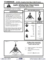
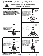
8,000 lb. Capacity Hook-Type Cable Sheaves
SAFE OPERATING PRACTICES
SAVE THESE INSTRUCTIONS
R1
R2
T
T
CL
ANGLE
A
ANGLE
B
ANGLE
D
ANGLE
C
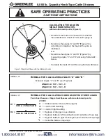
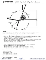
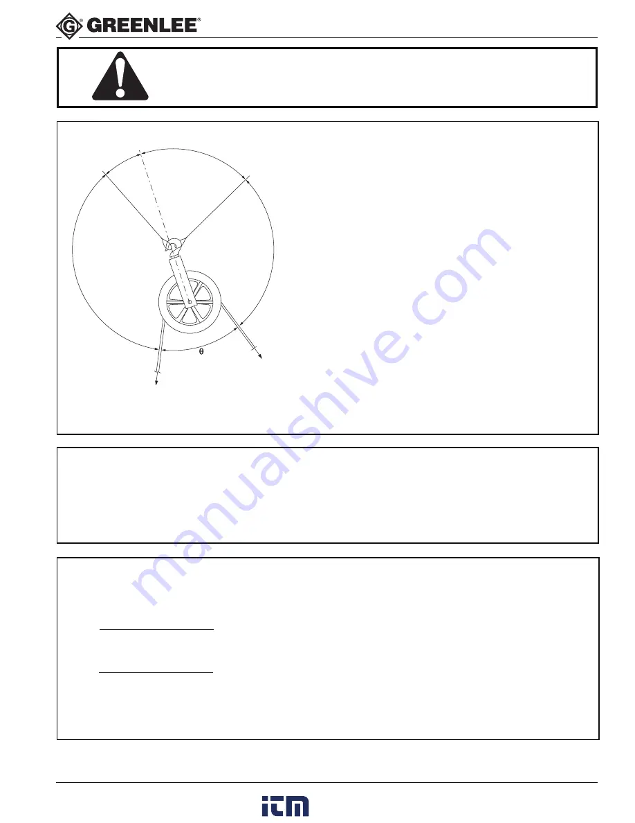
Figure 2 - Single Hook Sheave with two attachment points
FORMULA #2
CALCULATING THE LOAD ON
SINGLE HOOK SHEAVES
with two attachment points (Figure 2)
• Determine the load on the sheave from Chart #1
“Quick Reference Chart” or Formula #1 (page 3).
• Determine the angles “A” and “B” (Figure 2) by
extending an imaginary line beyond the yoke as
illustrated
OR
• Determine the angles “A” and “B” (Figure 2) by
measuring angles “C” and “D” and using Formula #2
below.
• Calculate the loads R1 and R2 using Formula #3 below
FORMULA FOR CALCULATING ANGLES “A” AND “B”
Measure angles “C” and “D” (see Figure 2)
ANGLE A = 180
°
- 1/2
θ
- C
ANGLE B = 180
°
- 1/2
θ
- D
WHERE:
R
= Added Load on Sheave (from page 3)
R1 = Load on left mounting
R2 = Load on right mounting
θ
= Degrees of change in rope direction
A
= Degrees between left mounting line and centerline of rope legs
B
= Degrees between right mounting line and centerline of rope legs
L
= Centerline between rope legs
R
R1 =
COS A + SIN A/TAN B
R
R2 =
COS B + SIN B/TAN A
FORMULA FOR CALCULATING HOOKS AND STRUCTURES LOADS
(Twin Yoke Sheaves or Single Hook Sheaves with two attachment points)
C
FORMULA #3
www.
.com
information@itm.com
1.800.561.8187

