background image


gSKIN

®

 U-Value KIT: Instruction Manual 

3 / 12 


green

TEG

 AG 


Hofwisenstr. 50A


8153 Rümlang, Switzerland


T: +41 44 515 09 15


info@greenTEG.com


greenTEG.com


3.


Ready to measure in five minutes by following these steps 

1.


Connect the data logger to your computer via the USB cable provided. 

2.


Allow all drivers to be installed. 

3.


The  necessary  read-out  software  can  be  downloaded  from 

https://www.greenteg.com/Download-

Software/

 (use the password provided to you by greenTEG). Follow the instructions to install the software 

on  your  computer.  You  need  to  have  admin  rights  to  follow  all  necessary  steps  (right  click  on  option 
"Execute as Administrator"). 
Currently  the software  is compatible with  Windows

®

  only.  If you use a different  operating system, e.g. 

Mac OS

®

, UBUNTU

®

 etc., please have a look at our FAQ for some hints and additional information: 

https://www.greenteg.com/faq-heat-flux-sensing/

.  

4.


When you open the software, the home screen will appear (See Figure 2)

. Under “File” 

“Language” you 

can change the language settings from English to German or vice versa.  

5.


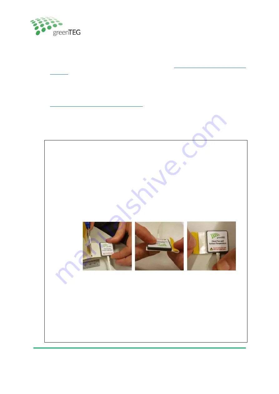
Mount the heat flux sensor onto the surface you would like to investigate. In the following box, we will 
briefly describe the mounting process. 
 

Short guideline on how to mount the sensors:


I.


Heat flux sensor placement 

a.


Install the heat flux sensor on the indoor surface with the side showing the gSKIN logo 
facing towards you. 
Use the adhesive roll tape. Mount the sensor on the exposed side of the tape. 
Completely cover the sensor with tape and cut an additional 2cm length of tape 
extending beyond the edge of the sensor (tip: when cutting tape, keep the exposed 
side of tape facing up). Fold back the additional length of tape onto itself to create a 
removal tab. Peel off the yellow protective film and mount the sensor onto desired 
surface. Firmly and evenly apply pressure on the sensor using your fingers for 4-5 
seconds to ensure good adhesion. Do not apply uneven pressure on the sensor with 
any hard objects. Ensure that the sensor is protected from direct heating, convection, 
and solar radiation. 


Figure 3 How to mount the sensor correctly 

b.


Optional: If the wall is wet or rough, use another adhesive (consult our online shop) 

c.


Optional: Use thermographic imaging to help identifying representative/interesting 
spots for the heat flux sensor placement on your building element. 

d.


Optional: Cover the heat flux sensor with the same material as its surrounding material. 

e.


Optional: Use several sensors to obtain an average value for highly inhomogeneous 
building elements. 
 

II.


Temperature sensor placement 

a.


Place the two temperature sensors at roughly opposite sides of the building element 
(i.e. wall or window) at the position where the heat flux sensor is placed. Use the 
provided double sided tape or another tape to mount the temperature sensors. 

Summary of Contents for gSKIN U-Value Kit

Page 1: ...Instruction Manual for gSKIN U Value Kit Status February 2020...

Page 2: ......

Page 3: ...ps 3 4 Six steps summary 8 Appendix A U Value software introduction 9 Appendix B Data Logger Characteristics 12 Appendix C Special Instructions for window U Value measurement 12 1 The gSKIN U Value KI...

Page 4: ...easuring process Before starting please select the frequency at which you would like to log your data points and when you want to start the measurement process logger stores up to two million data poi...

Page 5: ...door surface with the side showing the gSKIN logo facing towards you Use the adhesive roll tape Mount the sensor on the exposed side of the tape Completely cover the sensor with tape and cut an additi...

Page 6: ...process as indicated in step 9 before you stop your ongoing measurement The following box outlines the conditions which should be fulfilled for a successful measurement according to ISO 98692 Short o...

Page 7: ...e corresponding to secondary y axis Dotted vertical line Start of analysis period The section comments shows the comments made regarding your latest measurement activity see step 7 comments can be cha...

Page 8: ...all stored data There is no option to retrieve deleted data unless you have stored it before as a CSV msr file on your pc see step 12 15 To close the U value software you can select the Exit button o...

Page 9: ...gSKIN U Value KIT Instruction Manual 7 12 greenTEG AG Hofwisenstr 50A 8153 R mlang Switzerland T 41 44 515 09 15 info greenTEG com greenTEG com Figure 6 How to demount the sensor correctly...

Page 10: ...www u value greenteg com and watch our U Value KIT video Choose an optimal measurement spot on the building element of interest On the inside of this spot place the heat flux sensor and one temperatur...

Page 11: ...t analysis method the average method is introduced in section 7 1 of the standard It is the method used in the current software The average method is valid if certain conditions are met The heat conte...

Page 12: ...he U value report as generated by the U value software V1 02 04 Figure 9 demonstrates an example of a visualization of the data analysis procedure for a measurement duration of 8 5 days The analysis p...

Page 13: ...3s U value calculated by using the first 2 3 of the analysis period in days Number of days of this period is calculated using INT 2 3 D where D stands for the duration in days of the analysis period...

Page 14: ...tion 3 However a few points should be taken into account while performing glass measurements Measurements of the U Value according to ISO 9869 1 2014 standard section 7 1 can only be obtained if the m...

Page 15: ...vember 2014 5 December 2014 15 December 2014 5 January 2015 5 February 2015 25 February 2015 16 March 2015 28 October 2015 19 April 2016 12 July 2016 1 March 2017 14 May 2018 09 April 2019 1 November...

Reviews: