background image

INSTALLATION PREPARATION 

Page 16 


© 2013 Greenwood Clean Energy, Inc   All Rights Reserved V1.9 

NOTE:


Installation of this furnace must comply with the latest edition of NFPA 211 for 

reduced clearances and/or your local building code rulings (use whichever minimum 
dimensions are LARGEST). 

Contact your home insurance provider to ensure that installation is in compliance with local 
insurance requirements and all terms have been met. 


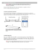
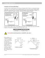
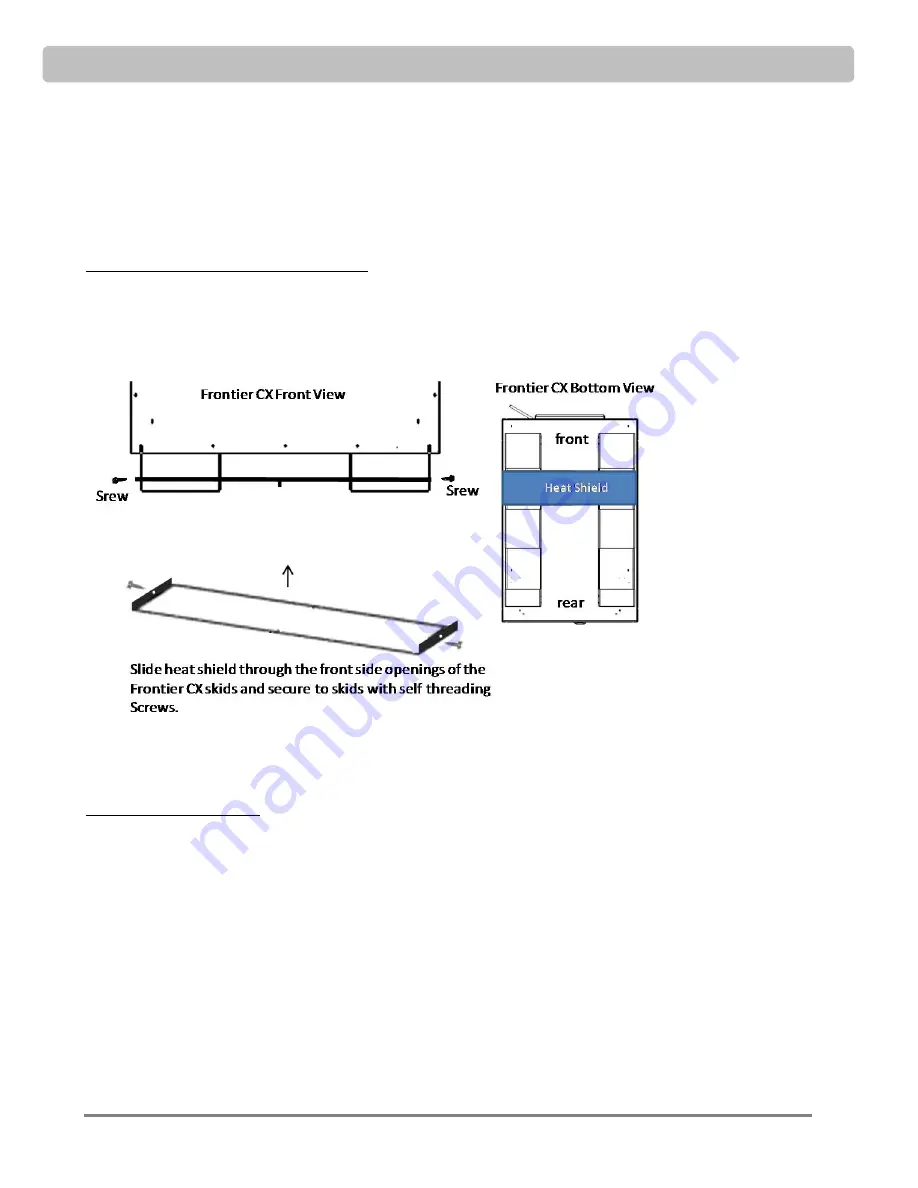
4. Install the Combustible Floor Heat Shield 

The Combustible Floor Heat Shield (part no. F100304) shipped with the Frontier CX is required to be 
attached when the appliance is installed on a combustible floor. The Heat Shield slides through the side front 
openings of the unit’s skids. Secure each shield in place with the self tapping screws. 


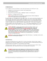
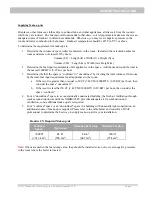
5. Install the Chimney Flue 

Refer to the “CHIMNEY INSTALLATION” section for detailed instructions.  Proper installation of the 
chimney flue is critical to the performance of your Greenwood Frontier hydronic furnace.  

Many of the 

problems encountered after installation are often attributable to a flue that is improperly sized or 
otherwise inhibits the draft to the furnace. 

NOTE:


There must also be adequate sources of make-up air for the room where the furnace 

is installed.  See “CHIMNEY INSTALLATION” instructions for more information. 


Summary of Contents for Frontier CX

Page 1: ......

Page 2: ...ation SAVE THESE INSTRUCTIONS READ THIS MANUAL AND KEEP IT NEAR THE FURNACE FOR REFERENCE V 1 9 2013 Greenwood Clean Energy Inc All Rights Reserved For the latest information about your Greenwood Fron...

Page 3: ...This page intentionally left blank...

Page 4: ......

Page 5: ...enwood Frontier CX Component Identification 11 11 INSTALLATION PREPARATION 12 Installation Requirements Checklist 12 1 Unpack and Inspect the Furnace 13 2 Unload the Furnace 14 3 Locate the Furnace 15...

Page 6: ...al Power Supply 33 Auto start Generator 33 Auxiliary Wiring for On Demand Zones 33 Auxiliary Wiring for Heat from a Backup Furnace or Boiler 34 OPERATING THE FRONTIER CX 35 Control System 35 Safe Prac...

Page 7: ..._ ___ ___ ___ ___ To identify your serial number see nameplate location on page 5 Dealer Name ____________________________________________________________ Address _____________________________________...

Page 8: ...SAFETY Page 4 2013 Greenwood Clean Energy Inc All Rights Reserved V1 9 SAFETY WARNINGS LABEL...

Page 9: ...SAFETY 2013 Greenwood Clean Energy Inc All Rights Reserved V1 9 Page 5 LABEL LOCATIONS...

Page 10: ...SAFETY Page 6 2013 Greenwood Clean Energy Inc All Rights Reserved V1 9 This page intentionally left blank...

Page 11: ...be familiar with local building codes fire codes and other regulations 2 Read this manual and learn how to safely operate and maintain your Frontier Series How the Greenwood Frontier Works The Fronti...

Page 12: ...ombustion temperatures 3 Crossfire Zone Over fire air is added following the separation of gases from the wood pile 4 Burn Out Zone Combustion is completed in the burn out zone where gas temperatures...

Page 13: ...the burn rate of the furnace balancing a clean burn heat demand 3 Fluid passing through the internal heat exchange manifold is heated by the exiting combustion gasses 4 The heated fluid enters the Fr...

Page 14: ...ity local climate type of wood burned etc Square footage based sizing is unreliable always base sizing on sustained output and heat loss calculations Greenwood Frontier CX Sizing The Frontier Series C...

Page 15: ...SPECIFICATIONS 2013 Greenwood Clean Energy Inc All Rights Reserved V1 9 Page 11 Greenwood Frontier CX Component Identification See Piping Section for piping component identification...

Page 16: ...s all draw air from the room Be certain there is an adequate source of fresh air to offset these demands or you may create negative pressure in the room and starve the furnace of air needed for combus...

Page 17: ...ver leaves If damaged list the issues and date on the shipping document and ask the driver to sign it Check the packing slip for a list of items shipped with the furnace some of the items will be foun...

Page 18: ...s in the lifting channels under the chassis with the forks spread to minimize the overhang on either side Move the loader as close to the furnace as possible without contacting the furnace with the li...

Page 19: ...sheet metal placed 1 Underneath the furnace 2 At least 16 inches 406 mm in front and 8 inches 203 mm on either side of the fuel loading and ash removal door and 3 Underneath the chimney connector and...

Page 20: ...CX is required to be attached when the appliance is installed on a combustible floor The Heat Shield slides through the side front openings of the unit s skids Secure each shield in place with the se...

Page 21: ...od Frontier hydronic furnace or in your home s heating system Always use propylene glycol based coolants rated for heating applications which contain the necessary additives to protect your system DO...

Page 22: ...e 6 to 5 Imperial Stove Pipe Reducer sold by Ace Hardware Product UPC 0634672300069 Chimney Height The Frontier Series is a forced draft system which means the induction fan will control the draft thr...

Page 23: ...minimum outward rise of 1 4 0 6 cm per horizontal 12 30 5 cm 3 If the connector stovepipe must go through a combustible wall before entering the masonry chimney consult a qualified mason or chimney de...

Page 24: ...t be at least 12 feet 3 7 m Furnace Min Flue Diameter Frontier CX 5 inches 12 7 cm Warning Solid wood burning furnaces should NOT be side vented When installing a new chimney flue be sure to observe l...

Page 25: ...ned or unconfined by dividing the total volume of the room by the total fuel input requirement for all appliances in the room a If the result is greater than or equal to 50 CF 1 42 CM 1000 BTU 0 29 KW...

Page 26: ...ng after 2 hours 4 Using the manometer measure the draft in the flue a If the draft measurement is below 05 WC 12 45 Pa at full fire there is too little draft and corrective measures are required to a...

Page 27: ...ospheric system While having the highest quality welds the heat exchanger is not an ASME certified pressure vessel Steps to connect the hydronic system 1 Connect the distribution loop to the supply an...

Page 28: ...System Part No 100110 NOTE All plumbing schematics shown in this section are for illustration purposes only Actual systems may require control and safety devices not shown in these illustrations Cons...

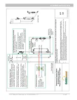
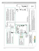
Page 29: ...PLUMBING INSTALLATION 2013 Greenwood Clean Energy Inc All Rights Reserved V1 9 Page 25 Pi ping Schematics...

Page 30: ...PLUMBING INSTALLATION Page 26 2013 Greenwood Clean Energy Inc All Rights Reserved V1 9...

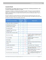
Page 31: ...mponents to meet the following requirements Hydronic System Functionality Frontier CX with install package Without install package Requirements Frontier Series Boiler Control System Outlet temperature...

Page 32: ...grains Nitrite is not included in our approved treatments as nitrites promote bacterial growth in vented systems Conductivity should not exceed 3 500 mmhos in treated water Without high nitrite levels...

Page 33: ...v 9100 Cleans cutting oil rust and solder flux from new systems Removes scale corrosion and bacteria from fouled systems See tech sheet Hydro Solve 9100 dilutes 1 50 so one to two gallons will be suff...

Page 34: ...be powered until the system is filled with fluid See diagram FW1 ThermSafeTM Overheat Cooling System The transformer that powers the system requires plugging into a 115 volt 60 cycle wall socket See d...

Page 35: ...WIRING 2013 Greenwood Clean Energy Inc All Rights Reserved V1 9 Page 31...

Page 36: ...Greenwood Boiler Management logic shuts down combustion and enables gravity fed cooling through the expansion tank when the power goes out or the outlet temperature rapidly rises beyond the set point...

Page 37: ...or more than a few pumps Cost will be proportional to duration of outage coverage Installation difficulty Moderate Additional electrical and plumbing work may be required Source www apc com Auto star...

Page 38: ...d by use of an additional aquastat and relay note these components are not included with the furnace The aquastat and relay keep the central furnace from firing unless there is insufficient heat comin...

Page 39: ...m The integrated Greenwood Boiler Management System is a micro processor based controller that continuously optimizes boiler performance The control system is designed to ensure safe operating conditi...

Page 40: ...and body well away from the door until it is completely open 6 BE CAREFUL when working around an open firebox door The vermiculite attached to the firebox door and the steel surrounding the firebox do...

Page 41: ...he firebox and void your warranty Place three small logs across the top of the newspaper and kindling supported by the two bottom logs ENSURE THAT FIREWOOD IS WELL SEASONED 1 Light the paper and kindl...

Page 42: ...verloading causes incomplete combustion of the fuel resulting in smoke and possibly a build up of creosote in the furnace This can potentially void the warranty on your furnace 5 Keep in mind the heat...

Page 43: ...protection whenever working around an open firebox door 4 Observe the following tips when feeding the fire a If a fire is burning let the wood load burn down as much as possible before refilling b Pr...

Page 44: ...nt factor in selecting a wood to burn We recommend using whatever wood is most economically available in your area Useful tips to help you in buying wood A cord is a stack of wood 4 feet 1 22 m high 4...

Page 45: ...14 7 Basswood 2 108 13 5 Beech Blue 3 890 26 8 Beech High 3 757 24 Birch Black 3 890 26 8 Birch Gray 3 179 20 3 Birch Paper 3 179 20 3 Birch White 3 179 20 3 Birch Yellow 3 689 23 6 Box Elder 2 797 17...

Page 46: ...ashes on the ground or place them in the garbage Hot Furnace 1 Wear protective clothing leather hearth gloves and eye protection 2 Open the firebox door and stir the ash to determine if live coals ar...

Page 47: ...e if needed to maintain a good seal 6 Exercise the safety relief valve at least once a year lift the handle and allow water to escape 7 DO NOT clean furnace surfaces when the unit is hot Wait until th...

Page 48: ...Lid by using a wrench to remove the lid nuts Lift off the lid using the lid handles Inspect the heat exchanger rope gasket for wear Contact your dealer to replace the gasket if it appears worn 5 Remo...

Page 49: ...chimney flue and blower housing 6 Clean the heat exchanger See above 7 Place a cap over the chimney to prevent birds and debris from entering 8 Clean the surface of the furnace with soap and water CA...

Page 50: ...all your dealer for service Error Light on Control Panel The control system is designed to ensure safe operating conditions and to initiate an automatic shut down in the event of an error If normal st...

Page 51: ...your dealer Creosote or Condensation is Forming Formation of creosote and condensation are not typical for the Frontier Series furnace and is a sign that the system is not performing optimally Green...

Page 52: ...ir intake lids fully close when solenoids powered off Inspect and remove any debris that may prevent the lids from closing completely flat Improper fuel Check the fuel wood you are burning Do not burn...

Page 53: ...d during high burn Do not open the door if there is a Red light under the Smoke Guard button is lit The Green Light indicates that The Smoke Guard button may be pushed and the door can be safely opene...

Page 54: ...WA This page intentionally left blank...

Page 55: ...mount paid by Greenwood based on time since year of purchase Product Yr 1 Yr 2 Yr 3 Yr 4 Yr 5 Yr 6 Yr 7 Frontier Series 100 75 60 40 25 15 10 The installation of replacements parts or components under...

Page 56: ...This page intentionally left blank...
Page 57: ...This page intentionally left blank...
Page 58: ...c Furnace Installation and Operation V1 9 Issue Date September 2013 Part No D100100 Printed in USA GREENWOOD CLEAN ENERGY INC 13429 SE 30TH Street Suite A Bellevue WA 98005 USA 2013 Greenwood Clean En...

Reviews: