background image

L

N

L1

11

10

Double Pole 

Isolating Switch

SK200B2 Fan 

Terminals

L

N

N

L1

L

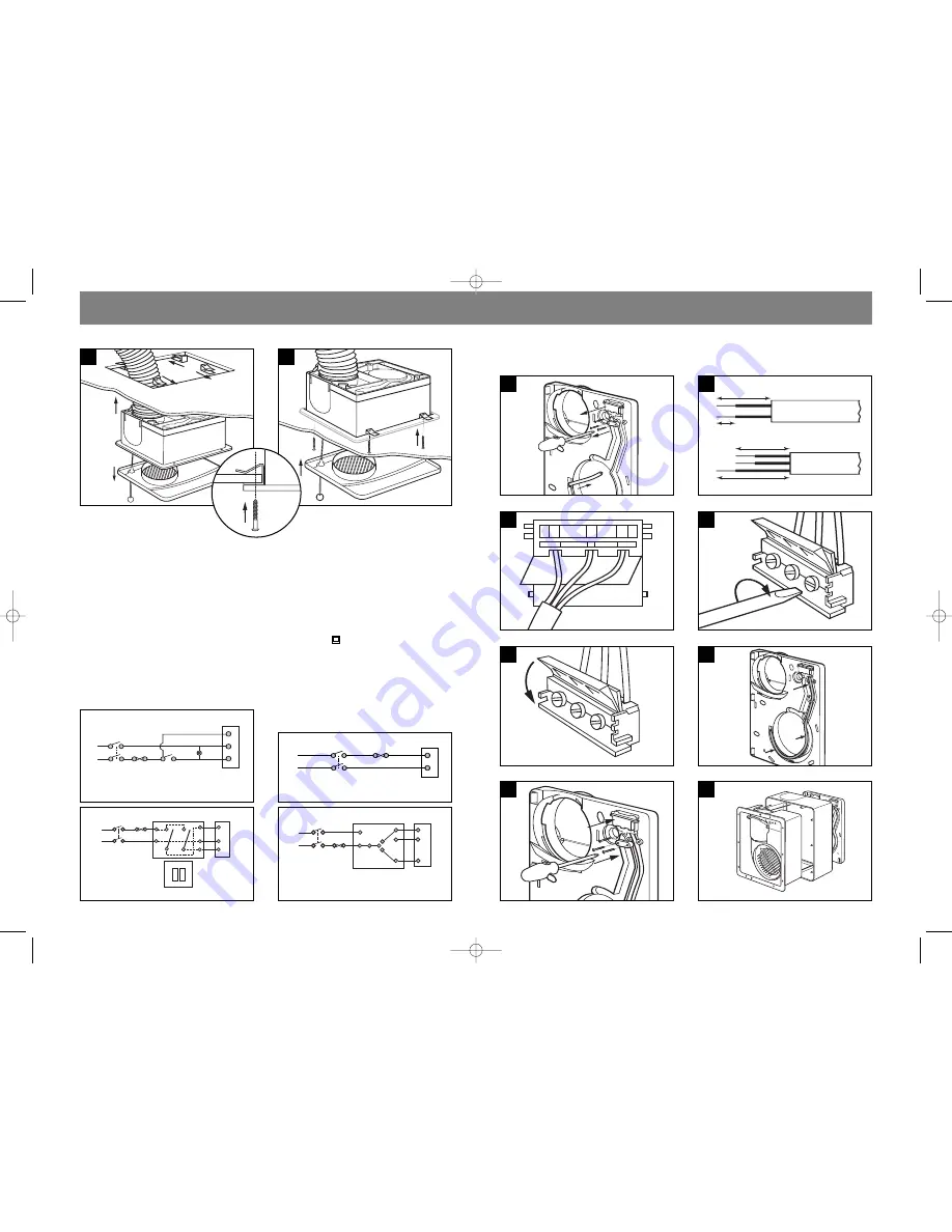
Wiring for SK200B2 – Connection with 2 gang switch.

Switch 2 Gang SP

Fuse 

OFF LOW

ON HIGH

The electrical connections must be carried out
by a qualified electrical engineer in accordance
with Part P of the Building Regulations & IEE
Wiring Regulations.

WARNING: Isolate electricity supply before
starting work.

The fans are double insulated and do not
require an earth connection.

NOTE:

Mains cable must be fixed back to the wall
using appropriate cable cleats.

Replace electrical cover.

NOTE: 

This equipment must be sited away

from direct water spray and heat in excess of
40

0

C, The controller must not be sited within

reach of a person using a bath or shower, nor
within a shower cubicle/enclosure.

The fans must be connected to a double pole
isolating switch having contact separation of
at least 3mm.

When supplied from a 6 amp lighting circuit
no local fuse is required.

Specification:

230 V ~ 50Hz.

Consumption:
SK200A

Max 36W Continuous 21W

SK200B2

Max 80W. Slow 22W

SK200MA

Max 80W. Slow 22W

SK200T

Max 80W

Mains Cable Sizes: 2 or 3 core.
0.75mm

2

and 1.00mm

2

.

Wiring Diagrams

1

3

5

8

35 mm

25 mm

6 mm

25 mm

3–Wire Connection

2–Wire Connection

1

2

1
2

3

2

4

6

Wiring Details for Fan Isolator Only

7

Rear of block

Front of block

L1

N

L

5

6

Use self-tapping screws. Plasterboard
thickness – max. 12mm, min. 9mm.

External wiring for pull cord only.

External wiring for operation in parallel with room  
light or remote switch with or without pull cord. 

Fuse

Double Pole 

Isolating Switch

Double Pole 

Isolating Switch

Double Pole 

Isolating Switch

Operating 

Switch

Light

(Optional)

Fan 

Terminal

Fan 

Terminal

Fuse

L

N

L1

L

N

Fan 

Terminal

L

N

N

N

N

L

L

L

N

1

3

4

L2

L1

E

External wiring for SK200B2 – 3 position
remote switch operation.

Remote switch

Fuse 

High

speed

Double Pole 

Isolating Switch

Fan 

Terminal

N

N

L

L

N

1

3

4

L1

L

External wiring for SK200B2 – GS1 – 3 position
remote switch operation.

Remote switch

Fuse 

High

speed

External wiring for pull cord only.

E

Double Pole

Isolating Switch

Double Pole

Isolating Switch

Double Pole

Isolating Switch

O

Fan

Terminal

Fan

Terminal

Fuse

L

Fan

Terminal

L

N

N

N

N

L

L

L

N

1

3

4

L2

L1

E

External wiring for SK200B2 – 3 position
remote switch operation.

Remote switch

Fuse 

High

speed

SK200 install AW 3.6.10  4/6/10  01:58  Page 10

Summary of Contents for SK200A

Page 1: ...nagement Ltd Greenwood House Brookside Avenue Rustington West Sussex BN16 3LF Tel 44 0 1903 771021 Fax 44 0 1903 782398 Email info greenwood co uk Internet www greenwood co uk Environmental Slotvent GW logo col_MASTER Environmental Slotvent Installation Instructions SK200 install AW 3 6 10 4 6 10 01 58 Page 1 ...

Page 2: ...peration by pull cord remote switch or light switch SK200MA Dual speed operation with humidistat to low speed with adjustable overrun timer to further reduce humidity Manual operation by pull cord remote switch or light switch to full speed without overrun timer SK200T Single speed operation by pull cord remote switch or light switch with overrun timer for adjustable time period To clean or servic...

Page 3: ...FITTING Cut out for surface mounted cabling A B Remove 2 screws Release cover with flat blade screwdriver A then apply thumb pressure to release catch in position B and gently pull free Fit 2 cover screws and tighten ensure corners clip into place Tighten 3 screws to secure Slide the top of the cover mounting clip into alignment Push cover in centre to engage centre clip Replace grille A B A B 12 ...

Page 4: ...first fix backplate and screw in position Fit front cover and secure with 2 screws supplied Fit 100mm duct and external grille baffle for soffit or wall application making sure duct has a slight fall to exterior Note Remove backdraught shutter flap if using flexible duct Ceiling Mounting Flexible Ducting External Grille or Airbrick GG42 or RAB DO NOT DISTORT BACKPLATE WHEN FITTING See page 10 for ...

Page 5: ...E Remove shutter flap if using flexible duct 4 3 SEE PAGE 10 FOR WIRING INSTRUCTIONS DO NOT DISTORT BACKPLATE WHEN FITTING SEE PAGE 10 FOR WIRING INSTRUCTIONS Template enclosed with fan must be used 4 3 NOTE Remove shutter flap if using flexible duct 6 7 Fit fan assembly as shown on page 5 pictures 10 11 12 SK200 install AW 3 6 10 4 6 10 01 58 Page 8 ...

Page 6: ... SK200T Max 80W Mains Cable Sizes 2 or 3 core 0 75mm2 and 1 00mm2 Wiring Diagrams 1 3 5 8 35 mm 25 mm 6 mm 25 mm 3 Wire Connection 2 Wire Connection 1 2 1 2 3 2 4 6 Wiring Details for Fan Isolator Only 7 Rear of block Front of block L1 N L 5 6 Use self tapping screws Plasterboard thickness max 12mm min 9mm External wiring for pull cord only External wiring for operation in parallel with room light...

Page 7: ...of purchase date 2 The Product has not been misused or handled carelessly or used on an inappropriate voltage supply 3 Repairs have not been attempted other than by Greenwood s service staff or authorised dealers and 4 In Greenwood s sole discretion the Product is found to be faulty If it were not found to be faulty the Product would be available for collection from the relevant Greenwood s premis...

Reviews: