background image

8.4

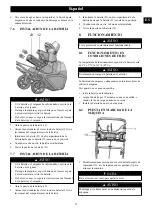
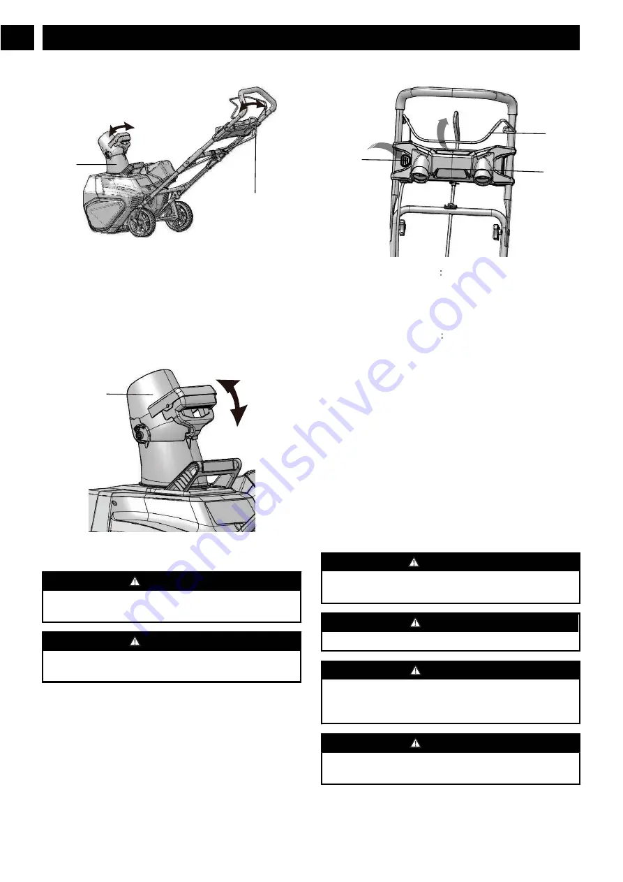
ADJUST THE DISCHARGE CHUTE

2

8

You can adjust the discharge chute 180° to change the snow
direction.

1. Turn the grip handle (2) left to move the discharge chute

(8) to the left.

2. Turn the grip handle (2) right to move the discharge chute

(8) to the right.

8.5

ADJUST THE CHUTE DEFLECTOR

11

You can adjust the chute deflector up and down to change the
throwing distance of the snow.


WARNING

Release the bail switch before you adjust the chute
deflector.


WARNING

Do not push the deflector so far forward that a gap shows
between the deflector and the chute.

1. Push and hold the trigger on the chute deflector (11).

2. Move the chute deflector (11) up to increase the snow

distance.

3. Move the chute deflector (11) down to decrease the snow

distance.

8.6

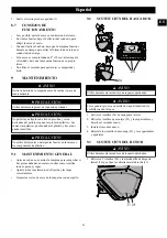
LED HEADLIGHTS

1

13

3

Turning the headlights on

1. Push and hold the safety switch button (13).

2. Pull the bail switch (1) in the direction of the handle bar

to turn the headlights (3) on.

Turning the headlights off

3. Release the bail switch (1).

8.7

OPERATION TIPS

If it is possible, clear the snow with the direction of the
wind.

In strong winds, lower the chute deflector to direct the
snow to the ground.

When you complete the work, let the machine operate for
a while to prevent ice formation in the discharge chute.

If the snow is deeper than 8", decrease the speed and let
the machine work at its own rhythm.

Do not use the scraper to remove compact snow and ice.

9

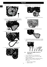
MAINTENANCE


WARNING

Remove the battery pack from the machine before
maintenance.


CAUTION

Use only approved replacement parts.


CAUTION

Do not let brake fluids, gasoline, petroleum-based materials
touch the plastic parts. Chemicals can cause damage to the
plastic, and make the plastic unserviceable.


CAUTION

Do not use strong solvents or detergents on the plastic
housing or components.

10

English

EN

Summary of Contents for SN60L01

Page 1: ...SNC403 1 23 5 725 0 18 612 7 52 5 6 0 18 23 5 25 48 32 48 7 1 9 SN60L01 SN60L6R1 SNC403 ...

Page 2: ......

Page 3: ... 012 3 0 ...

Page 4: ... 1 0 2 4 5 3 3 4 2 3 4 5 6 7 8 9 10 11 1 12 13 6 012 0 2 6 0 5 4 56 7 45 0 0 7 8 83 9 4 5 5 0 0 2 6 A 8 8 4 4 1B 4 2 2 C 2 7 5 4 B D 5 5 0 4 4 4 4 2 A 7 4 8 B 1 5 4 E 2 4 4 7 4 4 4 4 4 4 4 0 ...

Page 5: ...B 8 4 8 2 D C 2 2 D 9 C 8 8 2 4 4 8 4 7 4 2 G 8 G G1 183 81㸦 㸧 99H 7 5 4 5 0 0501 I 5 4 4 A D B C 7 4 4 5 C E 5 2 2 B 㸪 B 2 B B 1B J9 J B 9 G A 2 B 5 1 0 5 8 0 5 2 50 9 5 K9 5 K L K9 K K9 5 K L K9 K 6 K9 J L K9 K 5 K9 J L K9 K 6 5 K9 5 K L K9 K 0 ...

Page 6: ... 6 J9 J L J9 J 7 8 0 21 2 4 5 5 7 5 7 5 3 B 7 8 05 50 0 2 831 E5 4 4 4 7 8 05 50 0 7 8 83 E 5 4 4 4 8 E 5 4 4 4 8 7 5 5 03 0 0 5 7 56 85 7 5 B 7 8 83 2 B 6 0 5 4 4 1 4 5 0 ...

Page 7: ... 7 8 83 4 4 2 2 8 M 1 H 4 B 4 4 5 2 8 2 8 4 B 2 8 4 2 8 2 8 2 8 0 7 8 83 4 4 4 4 4 4 B 0 5 I I M B B 4 5 4 A 4 0 5 5 0 7 8 83 2 7 8 83 2 20 51 51 0 7 8 83 7 8 83 4 4 4 B B B 2 B 0 5 50 15 14 5 6 6 0 ...

Page 8: ... 0 5 2 50 14 15 4 5 0 5 1 2 6 1 11 16 17 19 18 0 5 1 2 1 0 20 21 22 17 0 5 85 7 51 12 23 0 ...

Page 9: ... 7 8 83 4 4 4 7 4 0 5 85 7 51 7 8 83 4 4 4 7 4 5 0 7 8 83 7 1 4 5 5 0 J9 5 J J9 J 7 8 83 2 6 4 4 5 51 0 1 13 7 4 8 1 0 7 8 83 7 8 83 1B 4 4 4 4 51 0 1 7 8 83 7 2 A 7 8 83 0 ...

Page 10: ... and hold the safety switch button 13 2 Pull the bail switch 1 in the direction of the handle bar to turn the headlights 3 on Turning the headlights off㸸 3 Release the bail switch 1 8 7 OPERATION TIPS If it is possible clear the snow with the direction of the wind In strong winds lower the chute deflector to direct the snow to the ground When you complete the work let the machine operate for a whi...

Page 11: ...cloth around the blade when you touch the blade 1 Remove the screws 24 from each side plate 2 Remove the mounting screws 25 and spacers and discard the old scraper 3 Install the new scraper 4 Reinstall the mounting screws 25 and spacers and tighten them 9 3 REPLACE THE IMPELLER WARNING Use only approved replacement scrapers 1 Remove the 5 screws 24 and side wear pad 26 that secure the right side c...

Page 12: ... height of the handle and make sure that the knobs and bolts are aligned cor rectly The machine does not start The battery is not charged Charge the battery by following the procedures in the battery and charg er manual The switch is de fective Have the switch replaced by an au thorized service center Battery is too cold Remove battery from snow throw er Place battery on charger and allow to charg...

Page 13: ... been hired or rented for industrial commercial use and that have been maintained in accordance with the instructions in the owners manual supplied with the product from new ITEMS NOT COVERED BY WARRANTY 1 Any part that has become inoperative due to misuse commercial use abuse neglect accident improper maintenance or alteration or 2 The unit if it has not been operated and or maintained in accorda...

Page 14: ...ar 3 R0200285 00 1 PCB board 4 R0200284 00 2 Cam Lock Assembly 5 R0200165 00 2 Wheel Assembly 6 R0200166 00 1 Control Rod Assembly 7 R0200173 00 1 Chute Deflector Assembly 8 R0200282 00 1 Scraper Kit 14 English EN 9 R0201918 00 1 Belt 10 R0201936 00 1 Motor 11 R0201937 00 1 Upper handle assembly 9 10 11 ...

Page 15: ... q 9 5 v 9 9 w 0 q w q 2 A 6 9 A 2 A 0 012 A q v w 3 x z ...

Page 16: ...1 35 0 5 2 3 4 5 6 7 8 9 10 11 1 12 13 F 0 012 2 6 5 3 01 5 0 5 2 5 5 5 5 0 5 1 15 F 0 1 4 3 1 6 51 0 8 A 0 A 0 9 2 8 A 8 A E A 4 A 4 E 8 0 C 8 A E 0 E A 1 A 4 B A 5 5 3 B E 4 4 4 B 8 0 E 4 A A E 8 E A B 0 E E B A E A 1 A A 1 z ...

Page 17: ... A 6201 05 0 8 E 1B E 4 1 2 B 4 A 4 E A E 4 A 8 2 A E A E 4 4 E 4 4 4 A E 1B 8 A 4 8 E 8 C A 8 A A 8 A C G A 8 E 8 A 2 A 4 8 E 4 2 1 A 8 3 1 10 H 1 A E 4 A B 2 A E A 50 0 0 4 4 4 E A A C 4 A 4 4 G A 8 A 0 B A 4 B 8 B B 0 B J9 J B 0 z ...

Page 18: ...5 K L K9 K A 5 4 K9 5 K L K9 K J9 J L J9 J J9 J L J9 J 4 K9 5 K L K9 K J9 J L J9 J 8 0 21 1 E 0 A 0 w q A 5 2 5 5 4 5 5 0 0 5 0 5 w q 5 A E E 5 5 5 2 0 3 0 B 8 0 151 0 0 6 15 10 3 5 A 4 5 4 2F1 185 5 A 4 5 4 1 8 5 A 4 5 4 1 8 5 A 5 051 0 85 5 2 5 5 5 5 8 0 z ...

Page 19: ...A E A q F 2 B 4 0 4 F 4 4 2 8 8 18 1 1 0 H 4 B 4 8 8 4 B 8 A 4 8 8 8 0 2 5 F 1 A 4 1 4 4 4 A A A 4 A I I A 1 B A A B A 4 E A 4 4 A 1 0 5 51 0 F 8 A F 8 A A E 85 5 5 2 05 F A F E 4 A E 4 A E E 4 0 A E A 2 z ...

Page 20: ... 0 5 51 0 5 5 0 5 15 14 5 6 6 EA 0 5 51 0 5 5 2 14 15 4 5 EA 0 5 51 0 6 1 1 0 21 11 16 17 19 18 E A 4 A E A A 0 5 51 0 5 35 5 1 0 1 0 21 20 21 22 17 E A A A B E z ...

Page 21: ... 3 EA A 0 5 51 0 5 85 5 12 23 F 4 2 A A 2 4 E A 4 0 5 51 0 5 85 5 F 4 2 A A 2 4 E A 4 6201 05 0 F 0 6201 05 0 0 1 0 1 0 6 0 J9 5 J J9 J F 8 B 0 E A A 4 E 4 E 2 5 0 5 1 5 5 2 05 1 13 4 A 8 6 A F A z ...

Page 22: ... F 1B 4 4 4 A 01 0 5 2 05 1 A F 1 A A 8 A F E 5 2 1 0 21 15 5 2 8 J 3 EA EA 3 5 2 6 1 1 0 21 11 E F F 8 A 21 50 5 1 13 3 9 5 9 z ...

Page 23: ...o y hacer que quede inservible PRECAUCIÓN No utilice disolventes o detergentes fuertes en la carcasa o los componentes de plástico 9 1 MANTENIMIENTO GENERAL Antes de cada uso examine la máquina para comprobar si hay piezas dañadas ausentes o sueltas como tornillos tuercas pernos y tapas Apriete todos los elementos de fijación y las tapas correctamente Limpie los restos de nieve de la máquina con u...

Page 24: ...32 26 9 4 ALMACENAMIENTO DE LA MÁQUINA Limpie la máquina antes del almacenamiento Asegúrese de que el motor no esté caliente cuando almacene la máquina Asegúrese de que la máquina no tenga piezas sueltas o dañadas Si es necesario siga estos pasos estas instrucciones Sustituya las piezas dañadas Apriete los pernos 24 Español ES 2 Retire la tuerca 27 9 Vuelva a instalar la placa lateral izquierda 32...

Page 25: ...16 in 40 6 cm Peso sin batería Batería LB602 LB6025 LB603 LB604 LB605 LB606 y otras series BAC Cargador CAC801 CH60DP01 CH60R00 60DPC10A y otras series CAC 12 GARANTÍA LIMITADA M E I L L E U R D A N S SA CATÉGORIE M EJ O R E N C L A S E BEST IN CLASS GARANTIE OUTIL BATTERIE GARANTÍA PARA HERRAMIENTAS Y BATERÍAS Por la presente Greenworks garantiza este producto al comprador original con el comprob...

Page 26: ...s Dirección en EE UU Greenworks Tools P O Box 1238 Mooresville NC 28115 13 VISTA DESPIEZADA Nº Nº pieza Cant Descripción 1 R0201935 00 1 Conjunto del rotor 2 R0200283 00 1 Barra de respaldo 3 R0200285 00 1 Placa de circuitos impresos 4 R0200284 00 1 Conjunto de cierre de leva 5 R0200165 00 1 Conjunto de las ruedas 6 R0200166 00 1 Conjunto de varilla de control 7 R0200173 00 1 Conjunto de deflector...

Page 27: ......

Page 28: ......

Reviews: