3.1.2
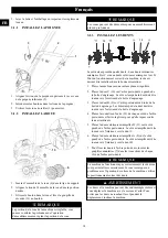
INSTALL THE WHEEL
13
6
1. Insert the wheel assembly(6) into the support rod.
2. Align the wheel assembly hole to desired position.
3. Slide bolt through hole and attach hitch pin(13) to bolt.
NOTE
The wheel position of the machine is adjustable.You can
control the depth of operation through adjusting the wheel
position.
NOTE
Wheels can be removed for greater tilling depth.
3.1.3
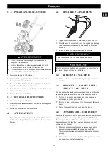
INSTALL THE TINES
12
12
The cultivator has four tines —two inner tines stamped B and
C and two outer tines stamped A and D. For correct operation
of the unit, the tines must be installed in the correct
orientation.
1. Put the machine on a flat and smooth surface.
2. Place tine C(10) on the tine shaft to the left of the gear
box. The stamped side of the tine should face away from
the gear box.
3. Place tine B(9) on the tine shaft to the right of the gear
box. The stamped side of the tine should face away from
the gear box.
4. Place a felt(12) washer on each side of the tine shaft, and
slide to rest against the inner tines.
5. Place the outer tine D(11) on the left side of the tine shaft.
The stamped side should face in toward tine C.
6. Place the outer tine A(8) on the right side of the tine
shaft. The stamped side should face in toward tine B.
7. To secure the tines to the tine shaft, insert the ring pins(7)
into the holes located on either side of the tine shaft.
NOTE
The unit will not operate properly if the tines are installed
incorrectly. If you notice a problem with the cultivating
operation of the unit, check for proper tine positioning.
WARNING
The tines and the machine may damage even if you move
the machine with the motor switched off. To prevent the
tines from touching the ground while moving please tilt the
machine.
3.1.4
INSTALL THE BATTERY PACK
WARNING
•
If the battery pack or charger is damaged, replace the
battery pack or the charger.
•
Stop the machine and wait until the engine stops before
you install or remove the battery pack.
•
Read and understand the instructions in the battery and
charger manual.
1. Open the battery door.
2. Align the lift ribs on the battery pack with the grooves in
the battery compartment.
3. Push the battery pack into the battery compartment until
the battery pack locks into place.
4. When you hear a click, the battery pack is installed.
5. Close the battery door.
8
English
EN
Summary of Contents for 27062
Page 2: ......
Page 24: ...No No de pièce Qté Description 52 32202144 1 VIS 24 Français FR ...
Page 36: ......


