background image

TOLL-FREE HELPLINE: 1-833-493-5483

www.greenworkselite.com

40V 14’’ Brushless String Trimmer 


Read all safety rules and instructions carefully before operating this tool.

Owner’s Manual

ST-140-T

Summary of Contents for EITE ST-140-T

Page 1: ...TOLL FREE HELPLINE 1 833 493 5483 www greenworkselite com 40V 14 Brushless String Trimmer Read all safety rules and instructions carefully before operating this tool Owner s Manual ST 140 T...

Page 2: ...and Part List 31 PRODUCT SPECIFICATIONS 40V 14 BRUSHLESS STRING TRIMMER Type battery powered Motor 40V Brushless Cutting Width 14 16 in 35 6 40 6 cm Line Diameter Nylon 0 08 Dual line Speed 6500 10 R...

Page 3: ...ommon sense Do not operate this unit when you are tired ill or under the influence of alcohol drugs or medication Store idle appliances indoors When not in use appliances should be stored indoors in d...

Page 4: ...rminals together may cause burns or a fire Under abusive conditions liquid may be ejected from the battery avoid contact If contact accidentally occurs flush with water If liquid contacts eyes additio...

Page 5: ...Use extreme care when approaching blind corners doorways shrubs trees or other objects that may obscure your view of a child who may run into the path of the trimmer W A R N I N G P R O P O S I T I O...

Page 6: ...bol min Per Minute Revolutions strokes surface speed orbits etc per minute Wet Conditions Alert Do not expose to rain or use in damp locations Read The Operator s Manual To reduce the risk of injury u...

Page 7: ...full face shield when needed We recommend a Wide Vision Safety Mask for use over eyeglasses or standard safety glasses with side shields Always use eye protection that is marked to comply with ANSI Z8...

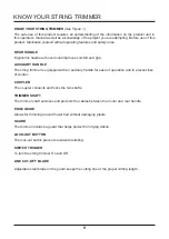
Page 8: ...8 KNOW YOUR STRING TRIMMER Fig 1 Rear handle Coupler Trimmer shaft Edge guide Guard Lock out button Switch trigger Auxilary handle Line cut off blade...

Page 9: ...with an auxiliary handle for ease of operation and to prevent loss of control COUPLER The coupler connects and locks the two shafts TRIMMER SHAFT The trimmer shaft encloses and protects the cables bet...

Page 10: ...rt Name Figure Qty String trimmer 1 Auxiliary handle 1 Guard 1 Edge guide 1 Auliliary handle screws 2 Trimmer guard screws 2 Operator s manual 1 UNPACKING This product requires assembly Carefully remo...

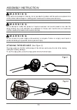
Page 11: ...mer Any such alteration or modification is misuse and could result in a hazardous condition leading to possible serious personal injury W A R N I N G Do not connect to power supply until assembly is c...

Page 12: ...pplied screws 1 from the trimmer head 4 with a philips screwdriver not included 3 Place the guard 2 on to the trimmer head 4 Align the screw holes on the guard 3 with the screw holes on the trimmer he...

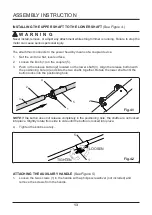
Page 13: ...n 2 located on the lower shaft 3 Align the release button with the positioning hole 4 and slide the two shafts together Rotate the lower shaft until the button locks into the positioning hole 4 2 3 1...

Page 14: ...sert and tighten the two screws so that the handle cannot be rotated on the shaft LINE TRIMMING CUT OFF BLADE See Figure 6 The trimmer is equipped with a line trimming cut off blade on the guard Repla...

Page 15: ...iarity with this product to make you careless Remember that a careless fraction of a second is sufficient to inflict serious injury W A R N I N G Do not use any attachments or accessories not recommen...

Page 16: ...7 Release the switch trigger and lock out trigger to stop the trimmer Press and hold the battery latch button 1 on the back of the battery pack While holding the battery latch place one hand the the...

Page 17: ...r Hold the trimmer with your right hand on the reat handle and your left hand on the auxiliary handle Keep a firm grip with both hands while in operation Trimmer should be held at a comfortable positi...

Page 18: ...personal injury W A R N I N G Read the safety information for safe operation when using a blade attachment and refer to the safety rules and instructions in your attachment manual Never use a brush cu...

Page 19: ...worn or damaged 4 Replace with a pre wound spool or replace line using 25 feet 8 meters of 0 080 inch 2 0 mm diameter line W A R N I N G Never use wire rope string etc which can break off and become...

Page 20: ...7 With your finger between the lines wrap the lines evenly and firmly around the spool in a clockwise direction 8 Position the lines in the guide slots 9 Place the spool in the cover as shown below Fi...

Page 21: ...of the cover 11 Reinstall the spool and cover onto the trimmer head Push until cover snaps into place REPLACINT THE BUMP KNOB See Figure 11 1 Remove the battery pack 2 Press the tabs simultaneously on...

Page 22: ...22 3 While holding the bump knob 1 firmly pry it out with a wrench 1 4 Replace with a new bump knob 1 Push the bump knob into the spool housing 2 2 1 OPERATION INSTRUCTION Fig 11 2 Fig 11 3...

Page 23: ...r Avoid cutting in the dangerous area shown in figure 12 Use the tip of string to do the cutting do not force string head into uncut grass Wire and picket fences cause extra string wear and breakage S...

Page 24: ...ANCE Maintenance task Each time the machine is used Every two hours Each week After use Every year or when required Visual check of the tool s safety systems distancing device carrying eye safety casi...

Page 25: ...e battery pack cracks or breaks with or without leaks do not recharge it and do not use Dispose of it and replace with a new battery pack DO NOT ATTEMPT TO REPAIR IT To avoid injury and risk of fire e...

Page 26: ...verly long cutting and motor overload 1 Remove the battery pack and mount the guard on the trimmer 2 Heavy cutting line is used 2 Use only with nylon cutting line 0 08 diameter or less 3 The motor sha...

Page 27: ...ement in this manual 5 The line is too short 5 Remove the battery and pull the lines while alternately pressing down on and releasing the bump knob 6 Bump head hit on the grass 6 Remove bump head hit...

Page 28: ...e to misuse commercial use abuse neglect accident improper maintenance or alteration or 2 The unit if it has not been operated and or maintained in accordance with the owner s manual or 3 Normal wear...

Page 29: ...29 EXPLODED VIEW 10A 11A 9A 7A 8A 6A 2A 1A 4A 3A 5A...

Page 30: ...T PCB BOARD 3A 311222475 1 KIT SWITCH TRIGGER 4A 311232475 1 KIT AUXILARY HANDLE 5A 311242475 1 KIT COUPLER 6A 311252475 1 KIT UPPER SHAFT 7A 311262475 1 KIT LOWER SHAFT 8A 311272475 1 KIT SPRING WIRE...

Page 31: ...Rev 00 09 22 17 TOLL FREE HELPLINE 1 833 493 5483 Greenworks Tools PO Box 1238 Mooresville NC 28115...

Reviews: