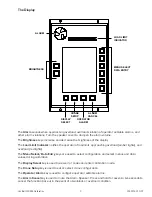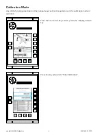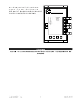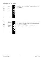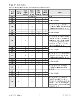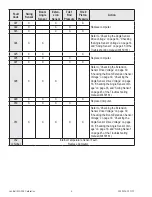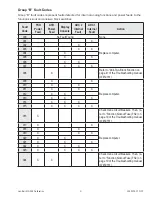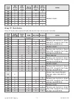
Link-Belt MG-534 Calibration
17
W450160 10/07
Menu 03 – Span
Boom Angle Sensor
IMPORTANT!
uSE gREAT CARE IN ThE CALIBRATION Of ThE BOOM ANgLE SENSOR. ALL SuBSEquENT
CALCuLATIONS ARE DEPENDENT ON ThE ACCuRACy Of ThE CALIBRATION Of ThIS SENSOR.
Fully retract the boom and raise it to an angle between 60 and 65 degrees. Measure the angle using
an inclinometer.
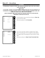
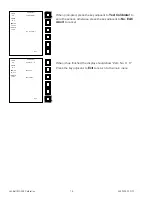
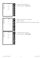
From the previous menu, press the key adjacent
Menu Up
to
go to “03 Span Sensor”.
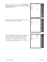
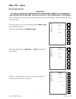
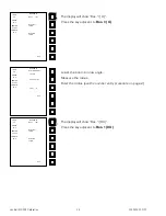
Press the key adjacent to
03 Span Sensor
.
Press the key adjacent to
Span No. 3 X.XX
(where X.XX =
actual input).
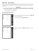
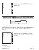
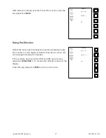
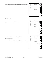
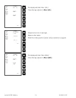
Enter the measured angle from the inclinometer (use the
number entry procedure on page 2).
LOAD
0.8
ANGLE
41.8
RADIUS
76.2 FT
LENGTH
106.0
03 Span Sensor
Menu Up
Menu Down
Exit
LOAD
0.8
ANGLE
41.8
RADIUS
76.2 FT
LENGTH
106.0
Span Sensor
Span No.3 0.00
Menu Up
Menu Down
Exit
LOAD
0.8
ANGLE
41.8
RADIUS
76.2 FT
LENGTH
106.0
Span Sensor
Enter Sensr Span
<0> 1 2 3 4 5 6
[ 63.50 ]
7 8 9 < . - C
Exit
Summary of Contents for MG-534
Page 1: ...Link Belt MG 534 Rated Capacity Indicator System Calibration...
Page 2: ......
Page 4: ...Link Belt MG 534 Calibration ii W450160 10 07...
Page 53: ...Link Belt MG 534 Calibration A 4 W450160 10 07...
Page 54: ......
Page 55: ......

