Link-Belt MG-534 Calibration
44
W450160 10/07
Menu 13 – Monitor
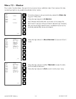
The monitor function allows the operator to view raw crane calibration data. This routine is for data
monitoring only! It is not possible to calibrate in this routine.
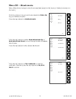
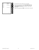
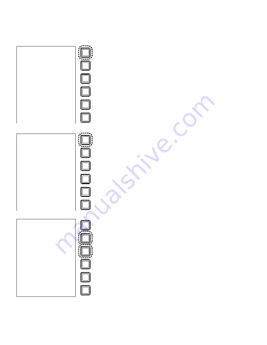
From the previous menu, press the key adjacent to
Menu Up
to go to “13 Monitor”.
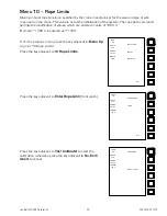
Press the key adjacent to
13 Monitor
.
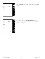
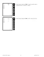
Boom Moment Data WG, WT, and Len-S can be viewed for
each boom mode (up to four) and each extension (up to seven).
Also, the Head Angle, BDC F-Factor, and BDC F-Factor for the
currently selected fly can also be viewed.
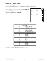
Press the key adjacent to
Boom Number
to view each boom
mode.
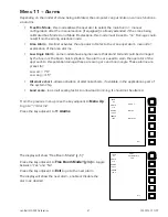
Press the key adjacent to either
Extension
to view the data
for the enabled extensions.
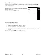
Press the key adjacent to
Exit
to return to the main menu.
LOAD
0.8
ANGLE
41.8
RADIUS
76.2 FT
LENGTH
106.0
13 Monitor
Menu Up
Menu Down
Exit
LOAD
0.8
ANGLE
41.8
RADIUS
76.2 FT
LENGTH
106.0
Boom Number :-0
BDC = -0.16
Monitor
Extn(0) = 0.0
Len_s(0) = 2.6
WG(0) =344.8
WT(0) = 25.5
Extn(0) = 0.0
Head Ang(0) = 0.0
BDC_fly = -1.59
Exit
LOAD
0.8
ANGLE
41.8
RADIUS
76.2 FT
LENGTH
106.0
Boom Number :- 0
BDC = -0.16
Monitor
Extn(1) = 12.0
Len_s(1) = 2.4
WG(1) =460.2
WT(1) = 21.1
Extn(0) = 0.0
Head Ang(0) = 0.0
BDC_fly = -1.59
Exit
Summary of Contents for MG-534
Page 1: ...Link Belt MG 534 Rated Capacity Indicator System Calibration...
Page 2: ......
Page 4: ...Link Belt MG 534 Calibration ii W450160 10 07...
Page 53: ...Link Belt MG 534 Calibration A 4 W450160 10 07...
Page 54: ......
Page 55: ......


