85
05.2012
DE
EU
FR
1
2
3
Tetra
Subject to technical modifications
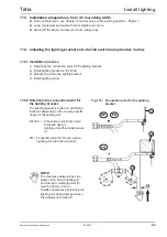
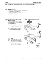
17.4.2 Determine the connection point for
the lighting bracket
17.4 Installing the lighting bracket onto the Tetra with dual spike disc harrow
Install lighting
17.3 Installation preparations, from 4.5 m working width
►
Fold out implement - see Chapter “Fold machine out into working position“ - Page 47.
►
Lower implement and ensure that it is stable and secure.
►
Switch off the tractor and secure it from rolling away.
17.4.1 Installation process
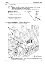
1) Determine the connection point for the lighting bracket.
2) Install lighting bracket on the Tetra.
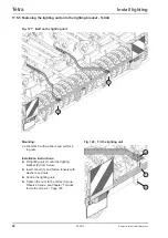
3) Bolt lighting unit to the lighting bracket.
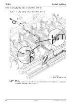
4) Install lighting wiring.
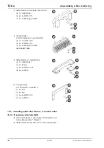
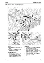
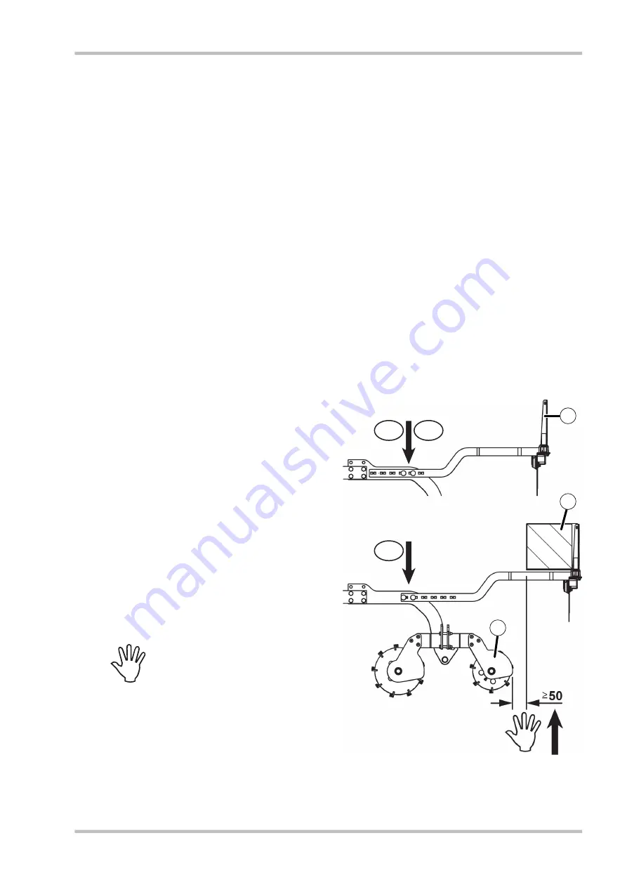
Fig. 119; Connection point for the lighting
bracket
The lighting bracket is bolted on at different
locations depending on the country-specific
design of the lighting unit.
DE / EU = Connection point for German /
European design.
Lighting unit without side panels
(1).
FR = Connection point for French version.
Lighting unit with side panels (2).
NOTE
The clearance between the side
plates of the French lighting (2)
and the rear crumbling roller (3)
must be 50 mm or more.
Smaller clearances will result in the
lighting unit being damaged when
the implement is folded in.
Summary of Contents for Tetra 3001 L
Page 4: ...05 2012 4 Tetra Subject to technical modifications ...
Page 104: ......
Page 106: ......
Page 107: ...107 05 2012 Tetra Subject to technical modifications 21 0 EU Declaration of Conformity ...
Page 108: ......
Page 110: ......
Page 111: ......


