background image


SRT 10/II 

USER MANUAL 

page 37 of 37 


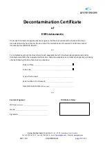
Decontamination Certificate 

of 

ESR Instruments 

 
Underneath named and signed executor engineer clarifies that concerned Instrument has been 

decontaminated as described in the document “Decontamination Procedure for ESR Instruments” 

documented as MAN-100-Rev.00. 
 

*** 

 
For completeness mark the check-box of each separated item if it has been decontaminated and/or 
disinfected and fill-in the requested information. Mention exceptions as remarks when (partly) not being 
able by following the decontamination procedure. 


Outer surface   


Tube area 


Type of instrument: 


Serial number of instrument: 


Decontamination date 

(dd/mm/yyyy)


*** 


Executor Engineer:


Distributor stamp:


Date 

(dd/mm/yyyy)


Name:   


Signature: 


Greiner Bio-One GmbH 


Bad Haller Str. 35 - 4550 - Kremsmuenster - Austria 

Tel.: +43 7583 6791-0 - Fax: +43 7583 6318 - E-mail

faq.at@gbo.com

 - Website

www.gbo.com


Summary of Contents for Sed Rate Timer 10/II

Page 1: ...0 II USER MANUAL page 1 of 37 Sed Rate Timer 10 lI SRT10 II including Software G2M110BO Vers 1 1 ESR Analyzer optional thermal printer available USER S MANUAL MAN 003 Revision 09 Revision date January...

Page 2: ...T NAME Sed Rate Timer 10 II SRT 10 II including Software G2M110BO Vers 1 1 Short cut name SRT 10 II Automatic Sed Rate analyzer 10 measuring channels Greiner Bio One GmbH Bad Haller Stra e 32 A 4550 K...

Page 3: ...4 READING PLATE 14 4 5 POWER SUPPLY 14 4 6 PRINTER 14 4 7 TEST TUBES 14 5 OPERATING PROCEDURE 16 5 1 READING PRINCIPLE 16 5 2 FUNCTIONAL SEQUENCE OF ANALYSIS 17 5 3 SAMPLE COLLECTING 18 5 4 LABELING...

Page 4: ...SRT 10 II USER MANUAL page 4 of 37 B PRINTER CONNECTOR 32 C DECONTAMINATION PROCEDURE 33...

Page 5: ...ger Please avoid handling electrical parts before disconnecting them from the power supply Never carry out maintenance on the instrument when it is under electrical tension Until the instrument is pac...

Page 6: ...acuum test tubes used for this instrument have been studied to draw the right level of blood To fill the test tube with a higher volume of blood could cause a serious infection risk for tube leakage F...

Page 7: ...ter box to assure correct usage Caution In vitro diagnostic medical device Consult instructions for use Biological risks See chapter 2 6 Disposal and recycling Electrostatic discharge sensitive device...

Page 8: ...o vibrations that could cause a false increase of results The bench must be flat and level Direct light on the instrument and sudden changes of temperature should be avoided Keep a free area of at lea...

Page 9: ...ble the internal fan 8 Enable power supply on printer connector DPT100 printer WARNING Do not switch on power when using a different type of printer as serious damage could be caused To enable each fu...

Page 10: ...raph OFF 7 Enable the internal fan ON 8 Enable power supply on printer connector DPT100 printer ON where x don t care has no effect 30 minutes analysis time N Switch Function Position 1 Enable 15 anal...

Page 11: ...ropriate cable and plugged in Connect and switch on first the printer then the SRT 10 II using the switch situated at the rear of the instrument Each time SRT 10 II is switched on it carries out an el...

Page 12: ...d electronic control Several seconds after the display will indicate Now the instrument is ready for the analysis On the display appears this message The top row will display the test time remaining p...

Page 13: ...laced by another so it is possible to analyze up to 40 tests h SRT 10 II has been developed to simplify ESR analysis avoiding sample manipulation and operator s infection risk To carry out the analysi...

Page 14: ...suggest for each sample the analysis time remaining time remaining symbols 4 4 Reading Plate One row of 10 test tube channels numbered from 1 to 10 4 5 Power Supply The low voltage supply built in ac...

Page 15: ...ime 30 min R2 0 970 D Automatic temperature conversion to 18 C Manley table Accepted range 15 C 32 C E Acceptable range for blood drawing 10 4 mm from normal F Measuring range 1 140 mm h G Memory capa...

Page 16: ...rise the software recognizes any positions occupied by samples containing the right level of blood At the first rising when the instrument has ensured that the meniscus is clearly distinct the level...

Page 17: ...7 5 2 Functional Sequence of Analysis TUBE DETECTION STAND BY TEMPERATURE DETECTION TEMPERATURE CORRECTION RESULTS INDEPENDENT READING PROCESS PRE INDICATION OF RESULTS CALCULATION READING TIME OPTION...

Page 18: ...he figure the test tube A has the correct blood level and the original label on which write patient code or other data if the barcode is absent The part H shows the zone that must be absolutely free a...

Page 19: ...new test tube The sample positioning on the analytic plate are numbered from 1 to 10 Numbering is meant progressively in groups of 10 samples so when the analysis of the sample in channel number one...

Page 20: ...b Write name or patient N on the tube and on the form following the channel position 4 After gently mixing for about 5 min put the tubes into reading channel following the form data 5 When the instru...

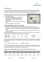
Page 21: ...compensation 1 Manley table correct values analysis temperatures ____________________________________________________________ 18 C 15 C 18 C 20 C 25 C 30 C 5 4 5 5 6 8 10 9 10 10 12 16 20 18 20 21 25...

Page 22: ...meaning the analysis start If after two minutes this symbol remains unchanged it means that the sample has been accepted by the level control made by SRT 10 II at the beginning of the analysis If the...

Page 23: ...initial level error rem Error removed sample 8 2 System Error Warnings This warning will be given if the instrument finds problems with the mechanical movement of the reading plate during the initial...

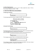
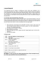
Page 24: ...ld fall into the test channel and obstruct a correct reading function during analysis 1 Wipe potentially contaminated areas of the SRT 10 II with a cloth or paper towel wet with 1 bleach solution Solu...

Page 25: ...instrument reading plate All other reading positions must be empty Turn on the instrument and wait The instrument detects this special condition and starts the self test After a while the reading plat...

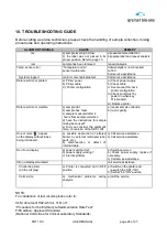
Page 26: ...measured after 4 hours from sample collection d have the instructions for sample mixing been used e Did you consider the automatic temp conversion of the SRT 10 II a repeat sample collection b re mix...

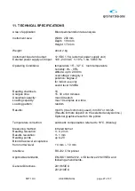
Page 27: ...dBA Reading chambers 10 Analysis time 15 30 or 60 minutes Analytical capacity max 40 tests h Loading capacity max 10 samples at a time Loading pattern random Results mm 1h most commonly used mm 30 or...

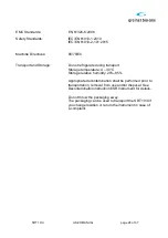
Page 28: ...during transport Storage temperature 4 30 C Storage relative humidity 20 85 Appropriate decontamination shall be performed prior to transportation removal from use and or disposal See Decontamination...

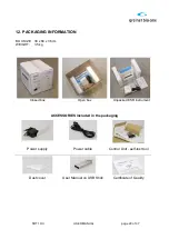
Page 29: ...G INFORMATION BOX SIZE 30 x 60 x 36 cm WEIGHT 3 5 kg Closed box Open box Unpacked ESR instrument ACCESSORIES included in the packaging Power supply Power cable Control Unit self test tool Dust cover U...

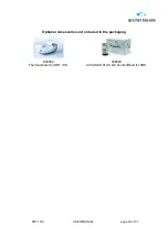
Page 30: ...SRT 10 II USER MANUAL page 30 of 37 Optional Accessories not included in the packaging 836582 Thermal printer for SRT 10 II 836595 ACCUSED PLUS QC Control Blood for SRS...

Page 31: ...prepared and well mixed is drawn into a Westergren tube up to the zero mark The tube is putted in the appropriate support and the erythrocyte level is read after 60 and 120 min A 2 Variations of ESR...

Page 32: ...dsberg J W 1935 A standardized technique for the blood sedimentation test American Journal of Medical Sciences 189 102 3 HARDWICKE J and SQUIRE J R 1965 The basis of the erythrocyte sedimentation rate...

Page 33: ...Bio One This also applies to the appended drawings and diagrams The contents of this instruction can also be changed without prior warning Greiner Bio One cannot be held responsible for any damage res...

Page 34: ...ination Certificate of ESR Instruments of this document should be filled in and signed by the executor which clarifies that this decontamination procedure has been followed as described in this docume...

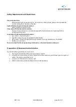
Page 35: ...h biohazard material Eye contact Flush with water Ingestion Report to nearest available medical facility Skin contact Wash thoroughly with soap and water use a germicidal soap if available Notify your...

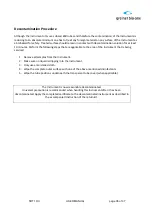
Page 36: ...re applicable to the area of the instrument that is being serviced 1 Remove all samples from the Instrument 2 Make sure no liquid is dripping into the Instrument 3 Only use a moistened cloth 4 Wipe th...

Page 37: ...ox of each separated item if it has been decontaminated and or disinfected and fill in the requested information Mention exceptions as remarks when partly not being able by following the decontaminati...

Reviews: