SRT 10/II
USER MANUAL
page 9 of 37
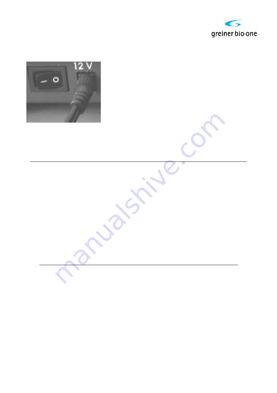
Connect the SRT10/II to the electricity supply by plugging the 12V power supply into the
intended power inlet on the SRT10/II. Only use the power supply provided.
3.3 Configuration
Before switching on the analyzer, please set-up the dip-switch placed in the rear panel
following the table below:
Switch Function
1
Enable 15' analysis time.
2
Enable 60' analysis time (works only if switch 1 = off)
3
Enable additional result formats (works only if switch 1 = off)
4
Enable temperature compensation
5
Enable the printer
6
Enable sedimentation curve graph
7
Enable the internal fan
8
Enable power supply on printer connector ( DPT100 printer )
WARNING!: Do not switch on power when using a different type of
printer, as serious damage could be caused.
To enable each function be sure that the corresponding switch is in the ON position. For
the analysis time and the results formats the following configurations are possible:
SW1
SW2
SW3
Analysis
time
Results format(s)
On
x
x
15'
mm/1hr
Off
On
On
60'
mm/2hr & mm/1hr & mm/30'
Off
On
Off
60'
mm/2hr
Off
Off
On
30'
mm/1hr & mm/30'
Off
Off
Off
30'
mm/1hr
(where 'x' = don't care, has no effect)
Example:
to configure instrument for 15 and 30 minutes analysis time, results corresponding to 1
hour Westergren, with temperature compensation, connected to the thermal printer (Item
number 836582), switches are placed: (Default Setting)


