background image

E40.0.01.6C-04 

Operating Manual EASY

LOG

 80CL 

Page 13 of 14 

13.  Device options 

Additi

onal information’s for options of the 

EASY

LOG

 80CL

13.1  ALARM 

With the o

ption „ALARM“ the device has an additional switching output (NPN) for  

the alarm function of the device. 
In result of the option there are following extensions: 

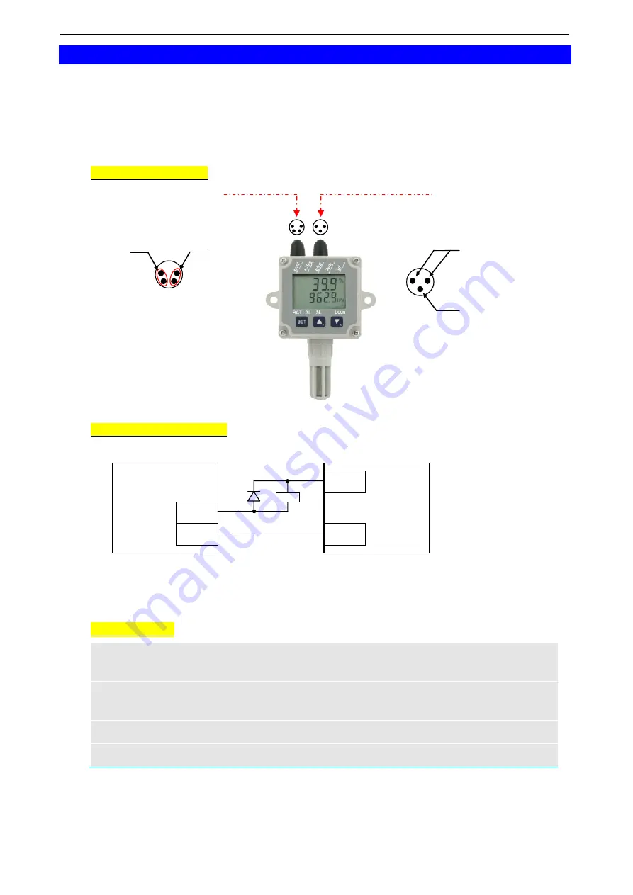
Device connection: 

Alarm output 

assignment of jack 

(view on pins) 

GND 

NPN 


Note to included alarm 
connection cable: 

GND:  back + blue 

NPN:  brown + white 


EASYBus 

assignment of jack 

(view on pins) 


EASYBus 


not used


Connection examples: 

a.)  General connection diagram for a relay (with self-induction recuperation diode): 


b.)  Connection information for GR 10, GNR 10 or GNR 232 A: 

GND:

  to be connected to terminal 11 of the 

GNR… 

NPN:

  to be connected to terminal 10 (or. 9) of the GNR... 

Specification: 

Alarm function: 

alarm points selectable within the measuring range 
and alarm delay adjustable from 0 to 500 min. 

Alarm: 

via display (AL.xx), interface communication and 
alarm output (transistor is conducting at alarm fault) 

Alarm output: 

open-collector 

max. switching power: 

28 V  /  50 mA 

Attention:  the alarm output is not electrically isolated 


When bus operating of several data loggers with option ALARM a  
electrical connection between the alarm outputs is not allowed!! 


EASY

LOG


alarm output 

NPN 

GND 

power supply 

(max. 28V)


-Ub 

+Ub 

Summary of Contents for 602773

Page 1: ...electronic GmbH D 93128 Regenstauf Hans Sachs Stra e 26 phone 49 9402 9383 0 fax 49 9402 9383 33 eMail info greisinger de ab f from Version V1 8 Operating Manual EASYLOG 80CL Data logger for humidity...

Page 2: ...logger EASYLOG 80CL is designed for long term monitoring of climate data Not only relative humidity temperature and air pressure can be displayed but also wet bulb tem perature dew point temperature...

Page 3: ...tentials 4 If there is any risk whatsoever involved in running it the device has to be switched off immediately and to be marked accordingly to avoid re starting Operator safety may be at risk if ther...

Page 4: ...play element for max min Logg indicates that logger is recording BAT signals weak battery see chapter 9 AL signals an alarm state at minimum one channel SL signals an active sea level correction for t...

Page 5: ...the display element MAX Note You can immediately switch to the next measuring channel pushing the button again Delete max value Push button for about 5 seconds CLr is displayed and the max values of...

Page 6: ...tart recording Push button for about 5 seconds The main display shows run The secondary display shows no To start recording select YES with the arrow keys button or and verify with Note If no key is p...

Page 7: ...ed if the logger is stopped logger without logger data 7 4 Operating possibilities via software EBxKonfig or EASYBus Configurator The software EBxKonfig V3 9 or EASYBus Configurator V2 0 is needed to...

Page 8: ...ow AL signals an alarm state at minimum one channel The arrow SL signals an active sea level correction 9 2 Logger status messages At stand alone operation no EASYBus connected logger status messages...

Page 9: ...er to the manufacturer for repair 9 4 Alarm and error messages The following messages correspond to a particular measuring channel and are dis played accordingly ALARM LOW The measured value is below...

Page 10: ...at range 10 90 RH Air pressure 1 0 mbar typ 2 5 mbar max Display two 4 digit LCD displays about 7 and 5 8 mm high Interface EASYBus Busload equals to 2 EASYBus elements Battery life time depending on...

Page 11: ...ng transparent screen made of polycarbonate splash proof acc to IP65 excl protection cap Sensor tube about 15 mm made of polyamide Protection cap removable twist plastic head made of polycarbonate IP4...

Page 12: ...oftware delete data Problem A error message is displayed Error message Possible reason procedure remedy measuring range exceeded Measuring range of the chan nel has been exceeded Operate logger within...

Page 13: ...tion diagram for a relay with self induction recuperation diode b Connection information for GR 10 GNR 10 or GNR 232 A GND to be connected to terminal 11 of the GNR NPN to be connected to terminal 10...

Page 14: ...E40 0 01 6C 04 Operating Manual EASYLOG 80CL Page 14 of 14...

Reviews: