background image

SECURE

connect 100

Strom- und Datenübertrager

Montage- und Bedienungsanleitung

Technisches Datenblatt

SECURE

connect 100

Power and Data Transmission Unit

Mounting and Operating Instructions

Technical Data Sheet

Seite 2

Page 29

Summary of Contents for SECUREconnect 100

Page 1: ...ct 100 Strom und Daten bertrager Montage und Bedienungsanleitung Technisches Datenblatt SECUREconnect 100 Power and Data Transmission Unit Mounting and Operating Instructions Technical Data Sheet Seit...

Page 2: ...ECUREconnect 100R Rahmenteil 13 6 Inbetriebnahme 15 6 1 Aufbau der Kommunikation 15 6 2 LED Signalisierung 16 6 3 Funktionen mit elektromotorischen Schl ssern 17 6 4 Funktionen mit elektromechanischen...

Page 3: ...ung Die Angaben dieser Bedienungsanleitung insbesondere die Kapitel ber Sicherheitshinweise sind unbedingt zu beachten Die Bedienungsanleitung ist nach dem Montageabschluss dem Betreiber zu bergeben L...

Page 4: ...Verschl sselte Daten bertragung Es gelten die allgemeinen Gesch ftsbedingungen der Fa GU SECUREconnect 100R zum Einbau in den T rrahmen Energie und Daten bertragungsger t f r motorische oder elektrom...

Page 5: ...itungsauslass beigef gte Kabelt lle verwenden Potenzialfreier Ansteu erkontakt z B Taster Sprechanlage Zutrittskontrolle Zeitschaltuhr Ansteuerm glichkeiten siehe Kap 6 Anschlusskabel mit Klemmen f r...

Page 6: ...tallation und Leitungsverlegung sind die Vorschriften und Normen f r SELV Span nung einzuhalten Bei Anwendung in Rauch und Feuerschutz T ren DIN 18250 ist das Schalten einer Dauerauf Funktion untersag...

Page 7: ...chenden Stulp mit den 8 mitgelieferten 4 x 7 Torx Spezielschrauben befestigen siehe Beutel Die Befestigungsschrauben d rfen nur mit geeignetem Werkzeug f r TORX T20 mit einem max Drehmoment von 1 0 Nm...

Page 8: ...htig zu entfernen sp ter wieder ankleben Die St elkontakten ragen jetzt 12 mm aus dem Ger t Bei Falzlufteinstellung 6 12 mm bitte Begrenzungsklammern nicht wieder einsetzen Um SECUREconnect 100F wiede...

Page 9: ...rstand an SECUREconnect 100 und Stulp durch das Ger t schieben lassen Ausreichend Platz f r eine Kabelschlaufe ber cksichtigen Achten Sie beim Befestigen des SECUREconnect 100 in der T r darauf dass s...

Page 10: ...n Vorgaben ausgef hrt werden 5 2 Allgemeine Beschreibung der Anschl sse SECUREconnect 100 Zum einfacheren Anschluss lassen sich alle Anschlussklemmen nach vorn abziehen 5 3 Beschreibung der Anschl sse...

Page 11: ...werden Dies kann z B f r einen beleuchteten T rknopf Stangengriff etc genutzt werden Der Stromausgang ist kurzschlussfest und auf 20 mA begrenzt so dass die LED ohne Vorwiderstand angeschlossen werde...

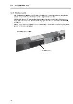
Page 12: ...Ger tes eingeschoben werden Der Modulschacht ist f r zuk nftige Anwendungen reserviert und wird nach Entfernen des Stulps durch Herausdrehen der 3 Stulpbefestigungsschrauben des SECUREconnect 100F zu...

Page 13: ...ussklemmen GU BKS NET Bus An die Klemmen LA und LB wird der GU BKS NET Bus angeschlossen ber diesen BUS kann SECUREconnect 100 mit anderen kompatiblen BUS Teilnehmern z B Fluchtt rsteuerung FTNT10 kom...

Page 14: ...so dass ein L sen verhindert wird Achtung Bei Metall und Kunststofft ren ist zur Leitungseinf hrung eine min 20 mm gro e Bohrung vorzusehen Die Bohrung muss mit der beiliegenden Kabelt lle zum Schutz...

Page 15: ...00 nach Anlegen der Betriebsspannung abwechselnd rot gr n Die Status LED am SECUREconnect 100F blinkt gr n wenn die T r einmal kurze Zeit ge schlossen und mit Spannung versorgt wurde Dies zeigt eine n...

Page 16: ...ikation mit anderen Ger ten am GU BKS NET Bus LED gr n 1 Hz blinkend Normalzustand codiert Kommunikation mit mindestens einem Ger t am GU BKS NET Bus LED rot 2 Hz blinkend Temperatur zu hoch LED rot 5...

Page 17: ...Schloss solange ge ffnet wie das Signal anliegt Wird die T r ge ffnet f hrt das elektrische Schloss die Falle nach 3 s wieder aus Wird die T r wieder geschlossen f hrt das elektrische Schloss die Fall...

Page 18: ...eschlossen wird der T rdr cker wieder eingekuppelt 6 4 2 T r Dauer AUF Wird ein an den Klemmen 91 V4 angeschlossener potenzialfreier Kontakt Tastimpuls bet tigt wird bei geschlossener T r an SECUREcon...

Page 19: ...wendig 1 manuelles Schlie en der T r 2 am SECUREconnect 100R die Versorgungsspannung z B 230V AC mittels EURO Stecker anlegen 3 am SECUREconnect 100R die braune und wei e Ader des Anschlusskabels br c...

Page 20: ...kabel Signal Grau blau GND minus Braun 24V plus Schwarz Steuerleitung SECUREconnect 100F 7 2 Anschlussplan Secury Automatik mit A ffner T r ffnungszeit bei Impulsansteuerung ca 2 s nicht einstellbar T...

Page 21: ...nnect 100R und 100F verbinden z B T r schlie en 6 Spannung am SECUREconnect 100R einschalten Es startet nun eine automatische Schaltsequenz die nach ca 30 s beendet ist W hrend die ser Zeit f hrt der...

Page 22: ...nal Blau verriegelt COM Rot verriegelt NO Schwarz entriegelt COM Violett entriegelt NO Grau rosa Schlie bart COM Rot blau Schlie bart NO Wei gr n Funktionsausgang COM Braun gr n Funktionsausgang NO Gr...

Page 23: ...Verriegelt COM Gr n Verriegelt NO Grau Verriegelt NC Rot Schlie bart COM Gelb Schlie bart NO Violett Dr cker Seite 1 COM Rot blau Dr cker Seite 1 NO Braun gr n Dr cker Seite 1 NC Wei gr n Dr cker Sei...

Page 24: ...iegelt COM Gr n Verriegelt NO Grau Verriegelt NC Rot Schlie bart COM Gelb Schlie bart NO Rosa Schlie bart NC Violett Dr cker Seite 1 COM Rot blau Dr cker Seite 1 NO Braun gr n Dr cker Seite 1 NC Wei g...

Page 25: ...hlussplan EK Schloss Serie 21 mit 8 poligem Anschlusskabel Anschlusskabel Signal Blau Verriegelt COM Grau Verriegelt NO Gr n Verriegelt NC Rot Schlie bart COM Gelb Schlie bart NO Wei GND Braun 12 24V...

Page 26: ...A LB V9 I1 V9 I1 V9 I2 V9 I2 V9 I3 V9 I3 V9 I4 V9 I4 NC NC COM COM NO NO NC NC COM COM NO NO NC NC COM COM NO NO NC NC COM COM NO NO IO10 1 IO10 2 Adressjumper Geschlossen Ger t 1 Offen Ger t 2 Adress...

Page 27: ...UF Eingang 4 Klemme I4 V9 7 8 2 Ausg nge am IO10 Modul Der Status der Eing nge SECUREconnect 100F wird direkt an die Relais des IO10 Moduls ausgegeben Grundeinstellungen Eingang SECUREconnect 100F Aus...

Page 28: ...sser Die Betriebsbereitschaft des Verschlusssystems ist regelm ig zu pr fen Hierzu m ssen die Befestigungspunkte berpr ft und die Schrauben ggf nachgezogen werden Die mechani schen Eigenschaften des S...

Page 29: ...SECUREconnect 100 Power and Data Transmission Unit Mounting and Operating Instructions Techncial Data Sheet 29...

Page 30: ...de component 41 6 Start up 43 6 1 Establishing communication 43 6 2 LED signalling 44 6 3 Functions with motor driven locks 45 6 4 Function with electromechanical locks EK 46 6 5 Electrical function t...

Page 31: ...specially the chapters concerned with safety should be observed After installation the instruction manual must be handed over to the operating company user who should read it carefully before operatin...

Page 32: ...rame and leaf Encrypted data transmission All deliveries are made on the basis of the General Terms and Conditions of the company GU SECUREconnect 100R for installation in the door frame Power and dat...

Page 33: ...ors use rubber grommet enclosed in package Potential free control contact e g pushbutton intercom access control timer switch For various control options see chapter 6 Connecting cable with input term...

Page 34: ...g cables Use enclosed rubber grommet on cable outlet from profile Observe standards and regulations for extra low voltage SELV during installation and laying of cables By no means switch a permanent O...

Page 35: ...the corresponding face plate each using the special 4 x 7 Torx screws included in the bag 8 altogether Tighten screws with a max torque of 1 0 Nm using a TORX T20 suitable tool only 4 2 Mounting the...

Page 36: ...travel must be removed carefully and re attached afterwards The tappet contacts now protrude 12 mm from the device Do not reinsert the restriction brackets with the rebate clearance set to 6 12 mm If...

Page 37: ...plate and SECUREconnect 100 without any resistance Ensure that there is sufficient space for a cable loop Be careful to not deform the face plate when fastening SECUREconnect 100 to the door this refe...

Page 38: ...specifications 5 2 SECUREconnect 100 terminals To facilitate connection all terminals can be disconnected from the front 5 3 Connection terminals of SECUREconnect 100F leaf side component 5 3 1 Termin...

Page 39: ...unlocked status This is useful e g for illuminated door knobs or push bars The power output is short circuit protected and limited to 20 mA which allows the LED to be connected without pre resistor Ap...

Page 40: ...the module compartment of the device Provided for future applications this compartment is accessible after removing the face plate from SECUREconnect 100F by turning out the fastening screws Further i...

Page 41: ...GU BKS NET bus Terminals LA and LB are assigned for the connection of the GU BKS NET bus This bus allows SECUREconnect 100 to communicate with other compatible bus participants e g escape door contro...

Page 42: ...to prevent it from coming loose Attention With metal and PVC doors it is necessary to drill a cable inlet with a minimum diametre of 20 mm The borehole must be fitted with the enclosed rubber grommet...

Page 43: ...pplied The status LED on SECUREconnect 100F flashes green as soon as the door has been closed once for a short time and supplied with voltage This indicates normal functioning At this stage the two SE...

Page 44: ...ication with other devices linked to the GU BKS NET bus LED green 1 Hz flashing Normal status coded communication with at least one device linked to the GU BKS NET bus LED red 2 Hz flashing Temperatur...

Page 45: ...ly the electrical lock remains open for the duration of the signal When the door is opened the electrical lock will extend the latch again after 3 s When the door is closed again the electrical lock w...

Page 46: ...oor is closed again the lever handle will be re engaged 6 4 2 Permanent OPEN If a potential free contact gating pulse connected to terminals 91 V4 is actuated with the door closed SECUREconnect 100F r...

Page 47: ...out the following work steps 1 Close door manually 2 Apply supply voltage to SECUREconnect 100R e g 230V AC by means of a Europlug 3 Bridge brown and white wire of connecting cable on SECUREconnect 1...

Page 48: ...gnal Grey blue GND minus Brown 24V plus Black Control line SECUREconnect 100F 7 2 Connection diagram Secury Automatik with A opener Impulse controlled door opening time approx 2 s cannot be adjusted P...

Page 49: ...5 Connect SECUREconnect 100R and 100F e g by closing the door 6 Switch on voltage on SECUREconnect 100R An automatic switching sequence will be started and completed after 30 s During this period of...

Page 50: ...ng cable Signal Blue Locked COM Red Locked NO Black Unlocked COM Purple Unlocked NO Grey pink Locking cam COM Red blue Locking cam NO White green Function output COM Brown green Function output NO Gre...

Page 51: ...e Signal Blue Locked COM Green Locked NO Grey Locked NC Red Cyl locking cam COM Yellow Cyl locking cam NO Purple Handle side 1 COM Red blue Handle side 1 NO Brown green Handle side 1 NC White green Ha...

Page 52: ...al Blue Locked COM Green Locked NO Grey LockedNC Red Cyl locking cam COM Yellow Locking cam NO Pink Schlie bart NC Purple Handle side 1 COM Red blue Handle side 1 NO Brown green Handle side 1 NC White...

Page 53: ...ction diagram of EK lock Series 21 with 8 wire connecting cable Connecting cable Signal Blue Locked COM Grey Locked NO Green Locked NC Red Cyl locking cam COM Yellow Cyl locking cam NO White GND Brown...

Page 54: ...LB G1 V1 LA LB V9 I1 V9 I1 V9 I2 V9 I2 V9 I3 V9 I3 V9 I4 V9 I4 NC NC COM COM NO NO NC NC COM COM NO NO NC NC COM COM NO NO NC NC COM COM NO NO IO10 1 IO10 2 Address jumper Closed Device 1 Open Device...

Page 55: ...rminal I4 V9 7 8 2 IO10 module outputs The input statuses SECUREconnect 100F are put out directly to the IO10 module relays Basic settings Input SECUREconnect 100F Output IO10 address 1 Input 1 termin...

Page 56: ...system must be verified at regular intervals For doing so check all all fixing points and retighten screws if required In order to avoid that the mechani cal properties of the lock especially with re...

Page 57: ...57 Power and Data Transmission Unit Notes...

Page 58: ...58 SECUREconnect 100 Notes...

Page 59: ...59 Power and Data Transmission Unit Notes...

Page 60: ...L0 0 Mod 2 Alle Rechte Irrt mer und nderungen vorbehalten All rights reserved Errors excepted Subject to change without notice Gretsch Unitas GmbH Baubeschl ge Johann Maus Str 3 71254 Ditzingen www g...

Reviews: