background image

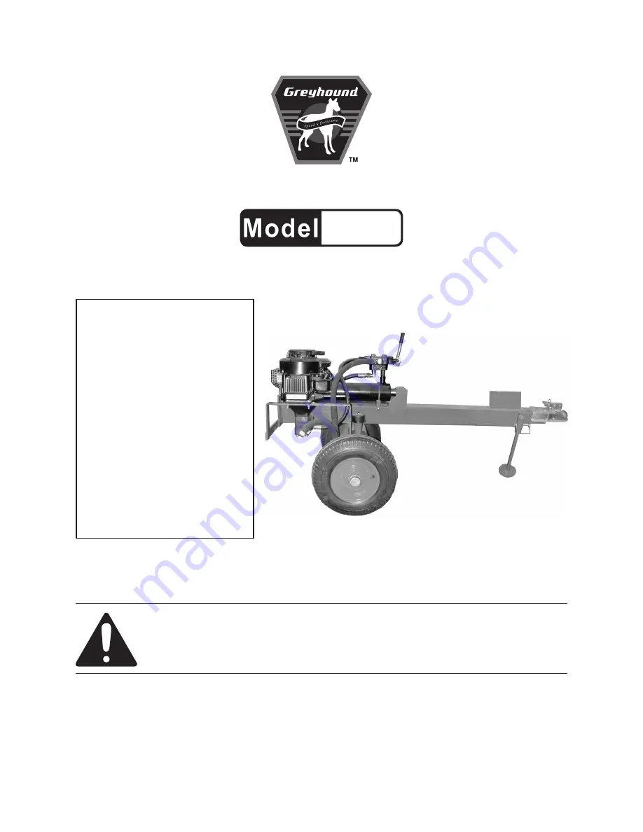
8 ton Hydraulic log splitter

66519

set up, operating, and servicing 

instructions

Warning!

iMportant inForMation

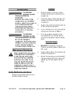
The Hitch Coupler MUST be properly 

secured  to  the  hitch  ball  of  the  towing 

vehicle.   After  assembly  and  attachment, 

pull up and down on the Hitch Coupler to 

make sure the hitch ball is fitting snugly in 

the Hitch Coupler.  

there must be no play 

between the hitch ball and Hitch coupler.


If there is play, tighten the Adjustment Nut 

until no play is present.  If the Adjustment 

Nut  is  too  tight,  the  Handle  will  not  lock.  

carefully read and follow the complete 

instructions  in  this  manual  BeFore 

setup or use.

if  the  coupler  is  not  secured 

properly, the ball could come loose 

while the log splitter is in motion, 

possibly causing property damage, 

serious  personal  injury,  or 

deatH.


distributed exclusively by Harbor Freight tools

®

.

3491 Mission Oaks Blvd., Camarillo, CA 93011

visit our website at: http://www.harborfreight.com

 read this material before using this product. 

Failure to do so can result in serious injury. 

save tHis Manual.

Copyright

©

 2009 by Harbor Freight Tools

®

.  All rights reserved.  No portion of this manual or any artwork 

contained  herein  may  be  reproduced  in  any  shape  or  form  without  the  express  written  consent  of 

Harbor Freight Tools.  Diagrams within this manual may not be drawn proportionally.  Due to continuing 

improvements,  actual  product  may  differ  slightly  from  the  product  described  herein.   Tools  required  for 

assembly and service may not be included.

For technical questions or replacement parts, please call 1-800-444-3353.

Summary of Contents for 66519

Page 1: ...me loose while the Log Splitter is in motion possibly causing property damage serious personal injury or death Distributed exclusively by Harbor Freight Tools 3491 Mission Oaks Blvd Camarillo CA 93011 Visit our website at http www harborfreight com Read this material before using this product Failure to do so can result in serious injury Save this manual Copyright 2009 by Harbor Freight Tools All ...

Page 2: ...ich if not avoided could result in minor or moderate injury NOTICE is used to address practices not related to personal injury CAUTION without the safety alert symbol is used to address practices not related to personal injury WARNING Read all instructions Failure to follow all instructions listed below may result in fire serious injury and or DEATH The warnings and precautions discussed in this m...

Page 3: ...off work area around the Log 4 Splitter to keep children and specta tors away during operation Never allow children to climb on or 5 play near Log Splitter even when not in use Observe work area conditions Do not 6 use machines or power tools in damp or wet locations Don t expose to rain Keep work area well lighted People with pacemakers should 7 consult their physician s before use Electromagneti...

Page 4: ...ired or under the influence of drugs alcohol or medication Do not overreach Keep proper foot 19 ing and balance at all times This en ables better control of the equipment in unexpected situations Dress properly Do not wear loose 20 clothing or jewelry Keep hair cloth ing and gloves away from moving parts Loose clothes jewelry or long hair can be caught in moving parts Parts especially exhaust syst...

Page 5: ...ngine that is sealed by the manufacturer or dis tributor Only a qualified service technician may adjust parts that may increase or decrease gov erned engine speed Wear ANSI approved safety goggles 4 heavy duty work gloves and dust mask respirator during service Maintain labels and nameplates on 5 the equipment These carry impor tant information If unreadable or missing contact Harbor Freight Tools...

Page 6: ...he beginning of this manual including all text under subheadings therein before set up or use of this product To prevent serious injury from accidental starting Slide the Fuel Valve of the equipment to its CLOSED position wait for the engine to cool and disconnect the spark plug wire s before assembling or making any adjustments to the equipment To prevent serious injury Operate only with proper s...

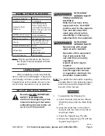
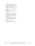
Page 7: ...with the Cotter Pin 16 Cover the end with the Dust Proof g Cap 15 Repeat steps h a through g for the other Wheel To assemble the Control Handle 36 2 Slide the Control Handle between a the U shaped bars on the direction Valve 41 Align the small hole on the side of b the Control Handle 36 with the holes on the Direction Valve 41 bars Insert the Pin 38 c Secure the Pin with the Clip 39 d ...

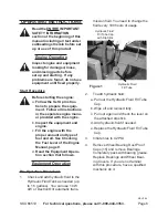
Page 8: ...ee Checking the Fuel Level of the Engine Manual page 9 Read the Equipment Opera d tion section that follows Equipment Operation Pre Operation Procedures Check and add hydraulic fluid to the 1 Hydraulic Fluid Tank as needed up to 1 5 gallons You can use 10 W AW or Dextron lll automatic trans mission fluid You need to change the fluid every 100 hours of usage Hydraulic Fluid Fill Tube Cap with Dip S...

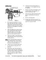
Page 9: ...e to neutral center position Note When using the Ram Control Han dle stand well clear of the cutting wedge and the area where the log will rest on the Main Body 23 Center a log on the Main Body 23 4 no more than 20 long and 14 in diameter Momentarily push forward lightly on 5 the Ram Control Handle until the log is locked in place between the Sliding Seat 33 and the Cutting Wedge If the log is cor...

Page 10: ...y to safely service the equipment or engine have a qualified technician service the equipment instead Engine Maintenance and Service Follow the instructions found in the included engine manual Storage Wait for engine to cool then clean 1 equipment with clean cloth and com pressed air Clean the engine and or prepare it for 2 storage according to engine manual instructions Apply a thin coat of rust ...

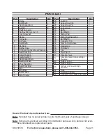
Page 11: ...art Description Qty 26 Nut M10 2 27 Support Leg Clip 3 28 Support Leg Pin 3 29 Support Leg 1 30 Baffle 2 31 Bolt M8x30 6 32 Sliding Pad 1 33 Sliding Seat Assembly 1 34 Bolt M8x70 1 35 Connector 12A 1 36 Ram Control Handle 1 37 Handle Grip 1 38 Pin B6x26 1 39 Clip 1 40 Pipe Clip 35 4 41 Direction Valve 1 42 Direction Valve Connector High Pressure 1 43 Rubber Hose I 1 44 Rubber Hose II 1 45 Oil Pump...

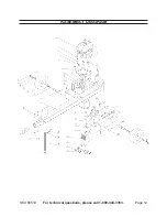
Page 12: ...SKU 66519 For technical questions please call 1 800 444 3353 Page 12 ASSEMBLY DIAGRAM ...

Page 13: ...o the buyer that he or she is qualified to make any repairs to the product or that he or she is qualified to replace any parts of the product In fact the manufacturer and or distributor expressly states that all repairs and parts replacements should be undertaken by certified and licensed technicians and not by the buyer The buyer assumes all risk and liability arising out of his or her repairs to...

Page 14: ...cidental or consequential damages so the above limitation of exclusion may not apply to you This warranty is express ly in lieu of all other warranties express or implied including the warranties of merchantability and fitness To take advantage of this warranty the product or part must be returned to us with transportation charges prepaid Proof of purchase date and an explanation of the com plaint...

Reviews: