Page 12
DLT 2.0 Differential Level Transmitter
CALIBRATION
Press
to
Calibration
and
to enter. Use
or
to position
before each menu item and
to enter. When settings are completed press
to
store and return to the
Calibration
menu.
Note - Sensors A & B do not need to be installed at the same height.
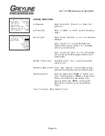
Sensor
Select either Sensor A or Sensor B for calibration.
Min Range
distance from the sensor face to highest expected level.
Max Range
distance from the sensor face to channel floor.
MaxVol
(Used for double tank monitoring applications, Volume and
HRT mode only. Enter the maximum volume of the vertical or
horizontal tank.
Note - to measure differential level the two sensors need a common reference
assumed to be a level channel floor.
Slope Offst
Appears when calibrating Sensor B. Enter a slope offset value
to compensate for a sloped channel floor. Offset will be a
positive value when Sensor B channel floor is lower than Sensor
A channel floor.
Damping
Minimum damping allows fast response to level changes.
Increasing damping slows the DLT 2.0's response to level
changes and is ideal to smooth the display and outputs in
turbulent conditions. Damping value is shown in percent (0-
99%). Some experimentation may be required to select the
optimum damping value. A value of 1% is recommended for
most applications and for fast level changes (up to ½ inch/sec -
13 mm/sec).
--Calibration-------
Sensor
B
Min Range
1.000ft
Max Range
12.000ft
Slope Offst
0.000ft
Damping
10%
LOE Time
30sec
}
SENSOR
‘
A
’
SENSOR
‘
B
’
M
I
N
RAN
G
E
M
I
N
RAN
G
E
MA
X
RAN
G
E
MA
X
RAN
G
E
SLOPE
OFFSET
BARS
C
REEN


