Page 7
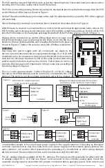
Only if
Setpoint
option installed
Setpoint
Act FWD
Setpoint
Res 1.0
°
<MENU>
Press to advance to next menu item
Use <UP> or <DOWN> to set the Setpoint Action to either FWD (forward)
or REV (reverse). FWD means that as the setpoint value increases the output
resistance increases. REV means that as the setpoint value increases the output
resistance decreases. Factory default is FWD.
Use <UP> or <DOWN> to set the Setpoint Resolution to either 0.5° or 1.0° as
required. The default is 1.0° which means that the setpoint will increase or
decrease by 1° for every button press. The display will be 21.0, 22.0, 23.0, etc
for example. For 0.5 resolution the display will be 21.0, 21.5, 22.0 for example.
Factory default is 1.0. This applies to both °C and °F operation.
17. SETPOINT ACTION
18. SETPOINT RESOLUTION
<MENU>
Press to advance to next menu item
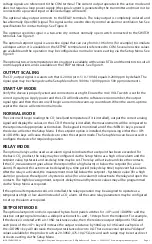
Calibrat Ref
1000 ppm
Calibrat
1000 ppm
The calibration reference screen allows user to set the calibration gas level used
for calibrating the sensor. Use <UP> and <DOWN> to adjust the ppm value of
calibration gas. The minimum value is 400ppm, the maximum value is 2000ppm.
Increment value is 50ppm for each step. Press <MENU> to save and advance. If no
calibration gas is available exposing the sensor to fresh outside can be used and
calibrate with 400PPM value. Another method is to determine the CO
2
ambient
level using a calibrated unit as a reference and adjust calibration setting to desired
value
The calibration screen is used for performing calibration of the sensor. To perform
calibration of the sensor place calibration hood over sensor housing and apply
calibration gas. Wait for several minutes and then press and hold <UP> or down
button for five seconds until display shows “Calibrat Done” or “Calibrat Fail”. Refer
to Calibration section in this document for more details.
<MENU>
Press to exit the menu and return to normal mode
<MENU>
Press to exit the menu and return to normal mode
19. CO
2
CALIBRATION
20. CO
2
CALIBRATION
CALIBRATION
Calibration with gas requires a field calibration kit (CDD1-CALKIT-GS) with pressure regulator, tubing,
sensor adapter and bottle of CO
2
gas. The certified calibration gas is applied directly to the CO
2
sensor to
perform a gas calibration.
Ensure the regulator knob is turned off and then hand tighten the regulator to the CO
2
gas bottle. A
length of tubing should be connected between the regulator output and the sensor adapter hood.
Remove the cover of the device to be calibrated to expose the gas sensor. Carefully install the sensor
adapter hood over the CO
2
sensor on the PCB. The adapter should fit snuggly and securely over the
sensor and remain in place during the entire calibration cycle. This will ensure a stable ppm CO
2
environment during calibration. Turn the regulator knob on to allow gas to flow to the sensor. The CO
2
reading on the LCD will begin to approach ppm level of calibration gas. Wait 3 to 5 minutes until the CO
2
reading stabilizes.
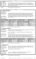
Setpoint
Mid 21
°
C
<MENU>
Press to advance to next menu item
Use <UP> or <DOWN> to select the Setpoint Midpoint. Units are either C or F
depending on the Temp Units setting.
Note that the setpoint has + or - 10 steps from the midpoint.
For °C, the midpoint range is 18 to 25°C (resolution = 1°C, default = 21°C)
For °F, the midpoint range is 64 to 77°F (resolution = 1°F, default = 70°F)
16. SETPOINT MIDPOINT
Copyright © Greystone Energy Systems, Inc. All Rights Reserved Phone: +1 506 853 3057 Web: www.greystoneenergy.com
IN-GE-CD2RMCXXX-04


