Page 2
WIRING
The transmitter has standard screw block connectors. Use shielded twisted pair wiring of at least 22 AWG
for all connections and do not run device wires in the same conduit with wiring used to supply inductive
loads such as motors. Disconnect the power supply before making any connections to prevent electrical
shock or equipment damage. Make all connections in accordance with national and local electrical codes.
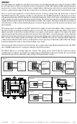
This is a 3-wire sourcing device. Connect the positive dc or the ac voltage hot side (24 Vac/dc ± 10%) to
the POWER terminal. The supply common is connected to the COMMON terminal. The device is reverse
voltage protected and will not operate if connected backwards. It has a half-wave rectified power supply
so the supply common is the same as the signal common. Several devices may be connected to one power
supply and the output signals all share the same common. Use caution when grounding the secondary of
a transformer or when wiring multiple devices to ensure the ground point is the same on all devices and
the controller.
The analog output is available on the OUT terminal. This signal is switch selectable for either voltage or 4-20
mA active output. In voltage mode the output is 0-5 or 0-10 Vdc, selectable in the User Menu. The current
output operates in the Active mode and does not require a loop power supply. This means the signal
current is generated by the transmitter and must not be connected to a powered input or device damage
will result. Check the controller Analog Input to determine the proper connection before applying power.
Both current and voltage signals are referenced to the COMMON terminal. The voltage output signal has
a minimum load that it is able to drive, similarly the current signal has a maximum load. Follow the ratings
in the Specification section or inaccurate readings may result.
The remote zero feature may be used by wiring a dry-contact (relay only) digital output between the ZERO
and COMMON terminals. Do not apply voltage to the ZERO terminal.
The RELAY output is a normally open dry contact. This signal can be used to directly control an alarm,
ventilation fan or may be connected to a digital input of the BAS for status monitoring. Ensure any loads
connected to the relay is within the relay rating in the Specification section.
Figure 5
mA
VOLT
MENU DOWN ZERO/UP
N.O.
RELAY
B+
A-
SHIELD
OUT
ZERO
PWR
COM
OUT
ZERO
PWR
COM
Analog Input
+24 Vdc
Common
Controller
Wiring all output signals and 24 Vdc power from controller
OUT
ZERO
PWR
COM
Analog Input
Common
Controller
Common
+24 Vdc
24 Vdc Power Supply
Wiring all output signals and external 24 Vdc power supply
OUT
ZERO
PWR
COM
Analog Input
Common
Controller
Common
+24 Vac
24 Vac Transformer
Wiring all output signals and external 24 Vac power supply
Figure 6
Figure 7
NO
RELAY
Digital Input
Controller
ZERO
COM
Digital Input
Controller
Figure 8
High
Low
Relay Output
Remote Zero
CURRENT
VOLTAGE
Figure 9
IN-GE-UPXXX-01 07/20
Copyright © Greystone Energy Systems, Inc. All Rights Reserved Phone: +1 506 853 3057 Web: www.greystoneenergy.com


