PRINTED IN C
ANAD
A
Page 6
SPECIFICATIONS
SENSOR
Accuracy ............................... ±1% F.S. of selected range @ 22°C (72°F) including hysteresis,
non-linearity and repeatability
Pressure Ranges .................
UPB1A:
±1", 0-1", ±0.5", 0-0.05" WC, ±250, 0-250, ±125, 0-125 Pa
UPB2A:
±0.25", 0-0.25", ±0.125", 0-0.125" WC, ±60, 0-60, ±30, 0-30 Pa
Stability ................................. ±1% F.S. (1 year)
Thermal Effect ..................... ±2% F.S. max, 10 to 40°C (50 to 104°F)
Response Time ................... 1-60 seconds, (menu selectable)
Proof Pressure .....................
UPB1:
100 "wc (24.9 kPa)
UPB2:
40 "wc (9.96 kPa)
Burst Pressure .....................
UPB1:
200 "wc (49.8 kPa)
UPB2:
80 "wc (19.9 kPa)
Operating Conditions ...... 0 to 60°C (32 to 140°F), 0-95 %RH non-condensing
Media Compatibility ......... Dry air or inert gas
Zero Adjust .......................... Pushbutton or digital input auto-zero
POWER SUPPLY
Power Supply ...................... 24 Vac/dc ±10%
Power Consumption .........37 mA max. with relay option
Input Voltage Effect .......... Negligible over specified operating range
Protection Circuitry ........... Reverse voltage protected and output limited
OUTPUT
Output Signal ......................
3 wire:
4-20 mA, 0-5 or 0-10 Vdc, field selectable
Output Drive .......................
4-20 mA:
750 Ω max
Voltage:
2K Ω min
LCD
Display Size ............................38.1 x 16.5 mm (1.5" x 0.65")
Digit Height ...........................11.43 mm (0.45")
Symbols ................................ "WC, Pa
Backlight ............................... Enable/disable/auto
ALARM FUNCTIONS
Alarm Relay Output .......... N.O. contact, 2 Amps @ 120 Vac or 30 Vdc
Alarm Relay Trip Point ...... Upper and Lower alarms adjustable over pressure range
Alarm Relay Delay ............. 0 to 10 minutes via keypad
GENERAL
Storage Temperature ........-40 to 95°C (-40 to 203°F)
Wiring Connections .......... Screw terminal block (14 to 22 AWG)
Pressure Connections ...... Barbed ports for 1/8" to 3/16" ID tubing
Conduit Connection ......... Access hole for 1/2" NPT conduit or cable gland
Enclosure .............................. Polycarbonate, UL94-V0, IP65 (NEMA 4X)
F style includes thread adapter (1/2" NPT to M16)
and cable gland fitting
Approvals ................................CE, RoHS
Country of Origin .................Canada
AUTO ZERO MODE
A sensor auto zero can be initiated by pressing and holding the internal <Auto-Zero> switch for at least
3 seconds. If both pressure ports are close to zero pressure, then the device will calibrate with a new zero
point. The auto zero can also be initiated by holding the ZERO IN terminal low for 3 seconds.
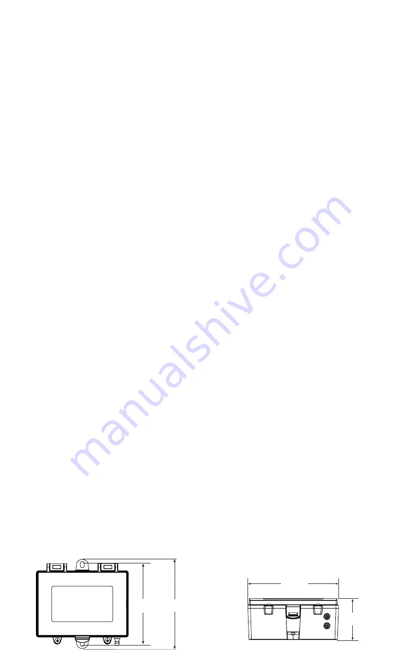
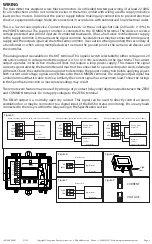
DIMENSIONS
112.5 mm
4.43"
99.7 mm
3.93"
53.7 mm
2.11"
116.5 mm
4.585"
IN-GE-UPXXX-01 07/20
Copyright © Greystone Energy Systems, Inc. All Rights Reserved Phone: +1 506 853 3057 Web: www.greystoneenergy.com


