background image

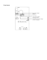
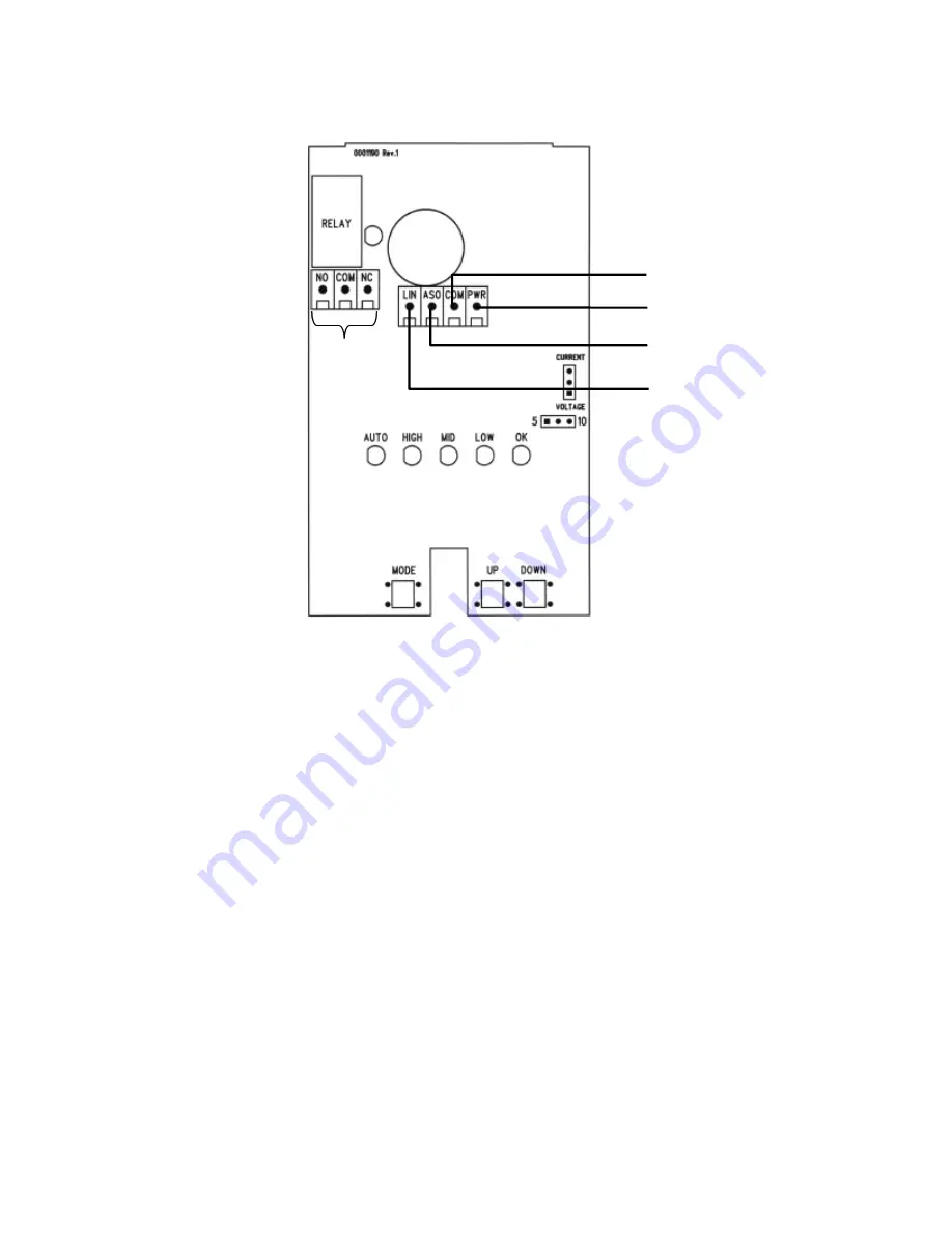
Wiring Diagram

Relay

Connection

(Optional)

20-30Vac/dc

Power Supply /Output
Common

Analog Stepped Output
(to damper actuator)

Linear Output (current or voltage)
(to B.A.S.) (Optional)

Summary of Contents for AIR-300

Page 1: ...AIR 300 Air Quality Controller Installation and Operating Instructions Febuary 15 2005 ...

Page 2: ...nants automatically control exhaust air on an assembly line where epoxies are used or a multitude of other applications Some common detectable pollutants in decreasing order of sensitivity most are easily detectable in quantities of 20 ppm or less Chemical Symbol Common Source Methyl Ethyl Ketone C4H8O Solvents and cleaning products Acetone C3H6O Solvents and organic synthesis Ethyl Alcohol C2H6O ...

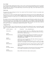
Page 3: ...m a ventilation fan or may be connected to a digital input of the B A S for status monitoring Start up Verify that the Air Quality Monitor is properly wired and all connections are tight Apply power to the device and note the status LEDs Initially the OK LED will be on and the AUTO LED will flash to indicate a four minute warm up cycle to allow the sensor to reach normal operating temperature The ...

Page 4: ...re or humidity extremes etc may cause dampers to stay open for long periods of time Auto Mode The auto mode factory default is selected by using the keypad and the Air Quality Monitor will operate in the Auto base Manual scale mode In this mode the base level is automatically adjusted by the program to ensure optimum air quality based on the surrounding environment and the air handling system The ...

Page 5: ... Once all connections are made and the warm up period has elapsed press the MODE switch once The OK LED will flash to indicate the mode and the ASO terminal will output an analog voltage corresponding to the OK pollution level This signal defaults to about 2 V and will drive the damper to open slightly to allow a minimum amount of fresh air into the area To modify this value simply press the UP or...

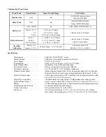
Page 6: ...nu so the relay will turn on when the linear output is Relay Level Relay Hysteresis and turn off at Relay Level Hysteresis Configuration Menu The Configuration Menu is used to set the operation mode relay modes and for calibration This menu is accessed during normal operation by pressing and holding the DOWN key and then pressing the UP key then release the keys This menu is explained below DOWN h...

Page 7: ...4 Vdc 200 mA 24 Vac 5 VA Max Input Voltage Effect Negligible over specified operating range Protection Circuitry Reverse voltage protected and output limited Operating Conditions 0 40 C 32 104 F 0 95 RH non condensing Standard Output Signal Analog Stepped Output ASO in four steps representing Ok Low Mid and High pollution levels each step is independently adjustable from 0 10 Vdc Optional Output S...

Page 8: ...Wiring Diagram Relay Connection Optional 20 30Vac dc Power Supply Output Common Analog Stepped Output to damper actuator Linear Output current or voltage to B A S Optional ...

Reviews: