background image

the supplemental tube matches the number as deter-
mined in step 2. Secure with the #8 self-tapping screw
into the bottom of the permanent tube.

NOTE: For ducts greater than 1

1

/

2

 feet in width, refer to sec-

tions [5.4.1] and [5.4.2].

Figure 2. Sampling tube connected to duct smoke
detector:

[5.3] Secure The Detector Housing To The Duct
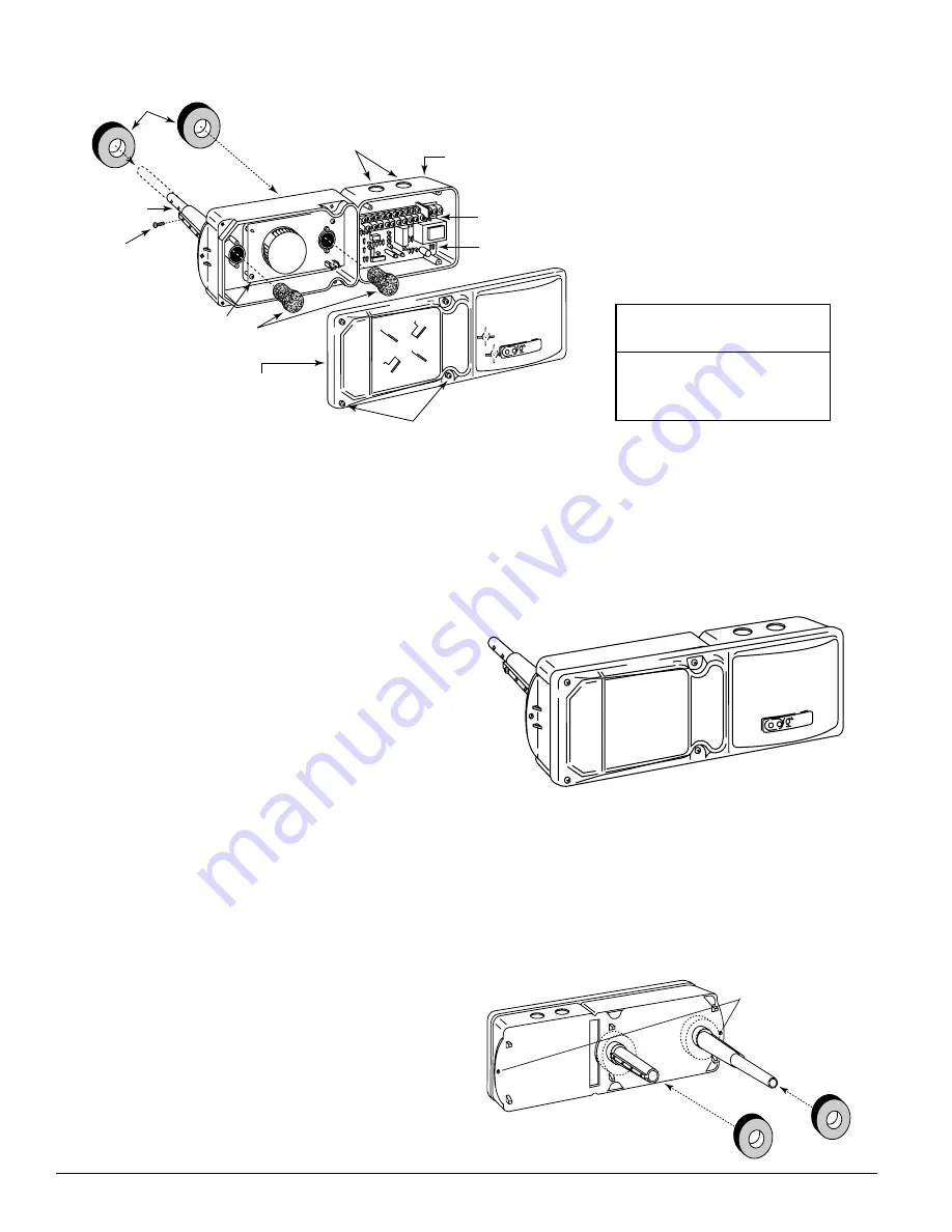
Slide the foam gaskets over the tube bushings as shown in
Figure 3. Use the two machine screws to screw the detector
housing to the duct. CAUTION: Do not overtighten the
screws.
Figure 3. Installation of foam gaskets over sampling
tube bushings:

SCREW HOLES FOR
ATTACHING HOUSING
TO DUCT WORK.

9. One inlet tube end plug
10. One telescoping sampling tube
11. One #8 self-tapping screw for the telescoping sampling

tube

NOTE: For ducts over 1

1

/

2

 feet, longer inlet sampling tubes

must be ordered to complete the installation. They
must be the correct length for the width of the duct
where they will be installed. See Table 1 on page 3
to determine the inlet tube required for different duct
widths.

[5] Installation Sequence
[5.1] Verify Duct Air Flow Direction And Velocity
Model DH100ACDCA detectors are designed to be used in
air handling systems having air velocities of 500 to 4000 feet
per minute. Be sure to check engineering specifications to
ensure that the air velocity in the duct falls within these pa-
rameters. If necessary, use a velocity meter to check the air
velocity in the duct.

[5.2] Drill The Mounting Holes
Remove the paper backing from the mounting template sup-
plied. Affix the template to the duct at the desired mounting
location. Make sure the template lies flat and smooth on the
duct. Center punch holes A and B. Drill the holes as indicat-
ed on the template. Insert the two jack nut receptacles.
Drive a #10 machine screw into jacket to flare the retainer,
then back out the screw to use for detector mounting.

[5.2.1] Sampling Tube Installation for Ducts Less
Than 1

1

/

2

 Feet Wide (see Figure 2)

1. Remove the front cover.
2. Use the tube installation chart above to determine the set

screw setting.

3. Slide the sampling tube into the housing bushing.
4. Align the holes in the bushing with the holes in the sam-

pling tube. Make sure the number of exposed holes on

D100-68-00

2

I56-1525-000

FOAM

GASKETS

PLASTIC

SAMPLING TUBE

CONDUIT HOLES

DETECTOR

HOUSING

TERMINAL STRIP

DETECTOR

COVER

SAMPLING TUBE

FILTERS

COVER MOUNTING

SCREWS

PLASTIC SAMPLING TUBE

SELF-TAPPING SCREW

POWER BOARD

DETECTOR BOARD

Tube Installation Chart:

Supplemental

Duct

Tube Holes

W i d t h

5

12”-14”

6

14”-16”

7

16”-18”

[3] Figure 1: Exploded View Of Duct Smoke Detector Components

Summary of Contents for DH100ACDCPA

Page 1: ...el interface alarm initiation HVAC control and other auxiliary functions Auxiliary relays are also provided for fan shut down or signaling of up to 9 other detectors in the loop for multiple fan shut down These detec For testing the alarm can be enabled by a magnet activated test switch or by the optional remote test station The duct smoke detector latches into alarm state when an alarm oc curs A ...

Page 2: ...s of 500 to 4000 feet per minute Be sure to check engineering specifications to ensure that the air velocity in the duct falls within these pa rameters If necessary use a velocity meter to check the air velocity in the duct 5 2 Drill The Mounting Holes Remove the paper backing from the mounting template sup plied Affix the template to the duct at the desired mounting location Make sure the templat...

Page 3: ...dth All other lengths must be purchased sepa rately Order the correct length as specified in Table 1 for width of the duct where it will be installed The exhaust tube is molded onto the base of the duct housing and the A2440 00 Exhaust Tube Extension is available as an accessory in those cases where the molded exhaust port does not ex tend at least 2 inches into the duct The inlet tube is always i...

Page 4: ...mation Replacement filters can be ordered from Sys tem Sensor 6581 Kitimat Rd Unit 6 Mississauga Ontario L5N 3T5 Exhaust tube intake tube filter P N F36 09 00 5 6 Field Wiring Wiring Installation Guidelines All wiring must be installed in compliance with the National Electrical Code and the local codes having jurisdiction Proper wire gauges should be used The conductors used to connect smoke detec...

Page 5: ...filters should be replaced because only a high percentage of con tamination affects performance If further testing is required compare differential pressure readings with and without the filters installed If the difference exceeds 10 replace the fil ters In no case should the pressure differential fall below 0 03 inches of water 6 2 Standby Alarm And Sensitivity Tests 6 2 1 Standby And Trouble Sta...

Page 6: ...FORMATION FOR WIRING OF AUXILIARY DEVICES REFER TO MANUFACTURER S INSTALLATION INSTRUCTIONS OR CONTACT MANUFACTURER NOTE THE SUPERVISORY RELAY NOW PROVIDES A FORM C CONTACT FOR CUSTOMIZED APPLICATIONS FOR STANDARD APPLICATIONS ONLY THE NO CONTACT IS USED POWER INPUTS ACCEPT 24 VDC 24 VAC 50 60 HZ 120 VAC 50 60 HZ OR 220 240 VAC 50 60 HZ CONNECT POWER SOURCE TO APPROPRIATE TERMINALS OF EACH DETECTO...

Page 7: ...ed with dirt replace them with new filters If they are not heavily coated use a vacuum cleaner or compressed air nozzle to remove dust then reinstall the filters 7 2 Photo Detector Boards 1 Remove the screen by gently grasping on each side and pulling straight off 2 Lift the photo chamber in the same fashion Vacuum the screen and cover Use clean compressed air to loosen and blow out any remaining ...

Page 8: ...cement 1 Disconnect wiring from the terminal block 2 Remove the two power board mounting screws 3 Pull gently on the board to remove it 4 To replace the board align the board mounting features holes and the interconnect terminals Push the board into place 5 Secure board with the two mounting screws 6 Re connect wiring to terminal block Power Supply Voltage 20 29 VDC 24 VAC 50 60 Hz 120 VAC 50 60 H...

Reviews: