12
6. Installation
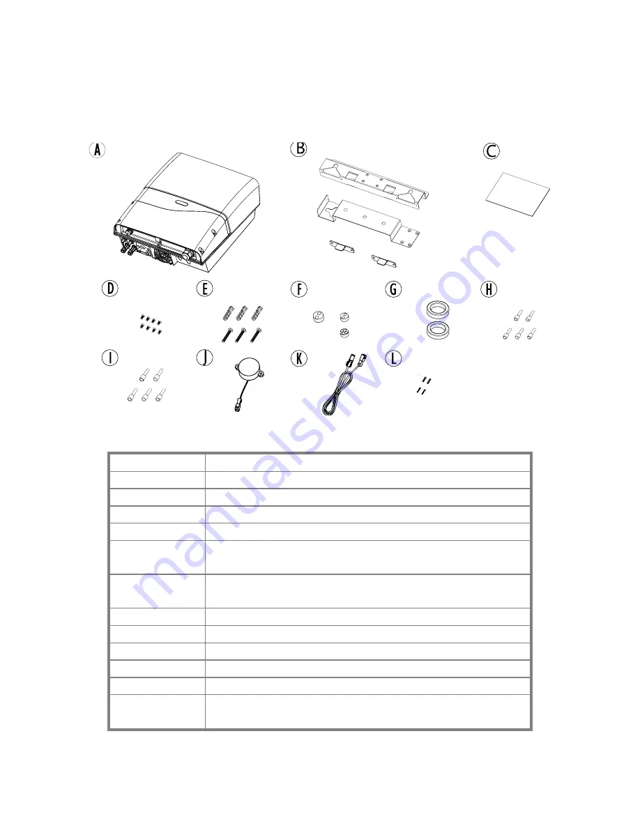
6.1 Unpacking PV-5000T-U/PV-8000T-U/PV-10000T-U
Item
Description
A
Inverter
B
Mounting Bracket Assembly
C
User Manual
D
M4 Flat Screws X 8, used for bracket
E
Plastic Anchor & Screws × 3. Used to fix bracket on
wall
F
Rubber Sealing for Ethernet, RS485, RCR and
buzzer wires. M25 × 1, M20 x 2
G
Clip-on EMI core for Ethernet cable
H
Insulated core end terminals (2.5 mm
2
) x 5
I
Insulated core end terminals (4.0 mm
2
) x 5
J
Buzzer for GFCI (Optional)
K
Extending wire for Buzzer (Optional)
L
2 pairs of anchors and screws for fixing buzzer
(Optional)
Summary of Contents for PV-10000T-U
Page 12: ...11 5 4 Product Labels ...
Page 14: ...13 6 2 Unpacking PV 15000T U ...
Page 15: ...14 6 3 1 Unpacking PV 20000T U ...
Page 16: ...15 6 3 2 Unpacking PV 20000T U E Display ...
Page 17: ...16 6 4 Assembly Chart PV 5000T U PV 8000T U PV 10000T U PV PV15000T U ...
Page 18: ...17 6 5 Assembly Chart PV 20000T U ...
Page 81: ...80 14 Addendum 14 1 Efficiency Charts 14 1 1 PV 5000T U 14 1 2 PV 8000T U ...
Page 82: ...81 14 1 3 PV 10000T U 14 1 4 PV 15000T U ...
Page 83: ...82 14 1 5 PV 20000T U ...
Page 84: ...P N MUB0 A00000 0 ...


