26
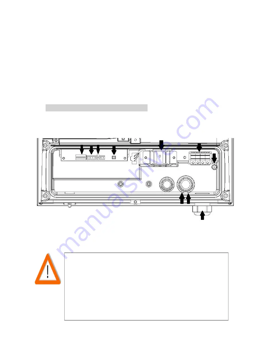
6.9.2.3 PV-15000T-U/PV-20000T-U (E-Display)
1.
Cable Gland- AC cables
2.
Cable Glands- RS485
3.
Cable Glands- external GFCI buzzer
4.
AC terminal block (PE or GND is located separately)
5.
Internal cooling fan
6.
RS485 terminal
7.
RS485 address selector and associated terminal switch
8.
Socket for external GFCI buzzer (reserved)
PV-15000T-U/PV-20000T-U (E-Display)
Note on AC Circuit Breakers
For safety reasons, place an independent circuit breaker
between inverter and grid BEFORE all connections. Make
sure inverter will be safely disconnected from the grid in all
circumstances. It is recommended to use certified 10A/250V
(PV-5000T-U) or 20A/250V(PV-8000T-U & PV-10000T-U) or
30A/250V (PV-15000T-U) or 35A/250V (PV-15000T-U &
PV-20000T-U) circuit breakers.
4
5
4
8
1
2
3
7
7
6
Summary of Contents for PV-10000T-U
Page 12: ...11 5 4 Product Labels ...
Page 14: ...13 6 2 Unpacking PV 15000T U ...
Page 15: ...14 6 3 1 Unpacking PV 20000T U ...
Page 16: ...15 6 3 2 Unpacking PV 20000T U E Display ...
Page 17: ...16 6 4 Assembly Chart PV 5000T U PV 8000T U PV 10000T U PV PV15000T U ...
Page 18: ...17 6 5 Assembly Chart PV 20000T U ...
Page 81: ...80 14 Addendum 14 1 Efficiency Charts 14 1 1 PV 5000T U 14 1 2 PV 8000T U ...
Page 82: ...81 14 1 3 PV 10000T U 14 1 4 PV 15000T U ...
Page 83: ...82 14 1 5 PV 20000T U ...
Page 84: ...P N MUB0 A00000 0 ...


