27
6.9.3 AC Wiring
1.
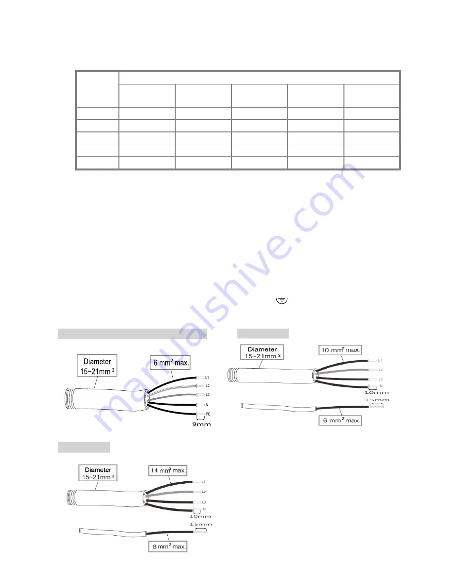
Prepare cables as recommended below
Cross
Section
(mm
2
)
Maximum Length for 1% Loss (M)
PV-5000T-U
PV-8000T-U
PV-10000T-U
PV-15000T-U
PV-20000T-U
2.5
17
11
9
N/A
N/A
4
28
18
14
N/A
N/A
6
42
26
21
14
N/A
10
N/A
N/A
N/A
23
17
14
N/A
N/A
N/A
N/A
24
Table above is based on single-core copper wires with maximum
temperature rise of 60°C. The following factors should be taken into
account when it comes to actual wiring:
Ambient temperature
Wiring nearby
Cooling
Please follow local standards if figures above are different from.
1.
Remove strip insulation ~ 9 or 10 mm
2
2.
Remove sealing plug, twist off the AC cable gland
3.
Insert AC cable through M32 rubber sealing and hole
4.
Fix L1 (Line 1), L2, L3, N (Neutral) and PE (
) on terminal block
5.
Tighten cable gland to secure cables in position
PV-5000T-U/PV-8000T-U/PV-10000-U
PV-15000T-U
PV-20000T-U
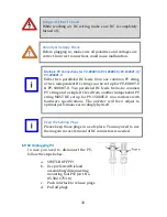
Summary of Contents for PV-10000T-U
Page 12: ...11 5 4 Product Labels ...
Page 14: ...13 6 2 Unpacking PV 15000T U ...
Page 15: ...14 6 3 1 Unpacking PV 20000T U ...
Page 16: ...15 6 3 2 Unpacking PV 20000T U E Display ...
Page 17: ...16 6 4 Assembly Chart PV 5000T U PV 8000T U PV 10000T U PV PV15000T U ...
Page 18: ...17 6 5 Assembly Chart PV 20000T U ...
Page 81: ...80 14 Addendum 14 1 Efficiency Charts 14 1 1 PV 5000T U 14 1 2 PV 8000T U ...
Page 82: ...81 14 1 3 PV 10000T U 14 1 4 PV 15000T U ...
Page 83: ...82 14 1 5 PV 20000T U ...
Page 84: ...P N MUB0 A00000 0 ...


