54
8.2.2 RS485 Segments PV-20000T-U (E-Display)
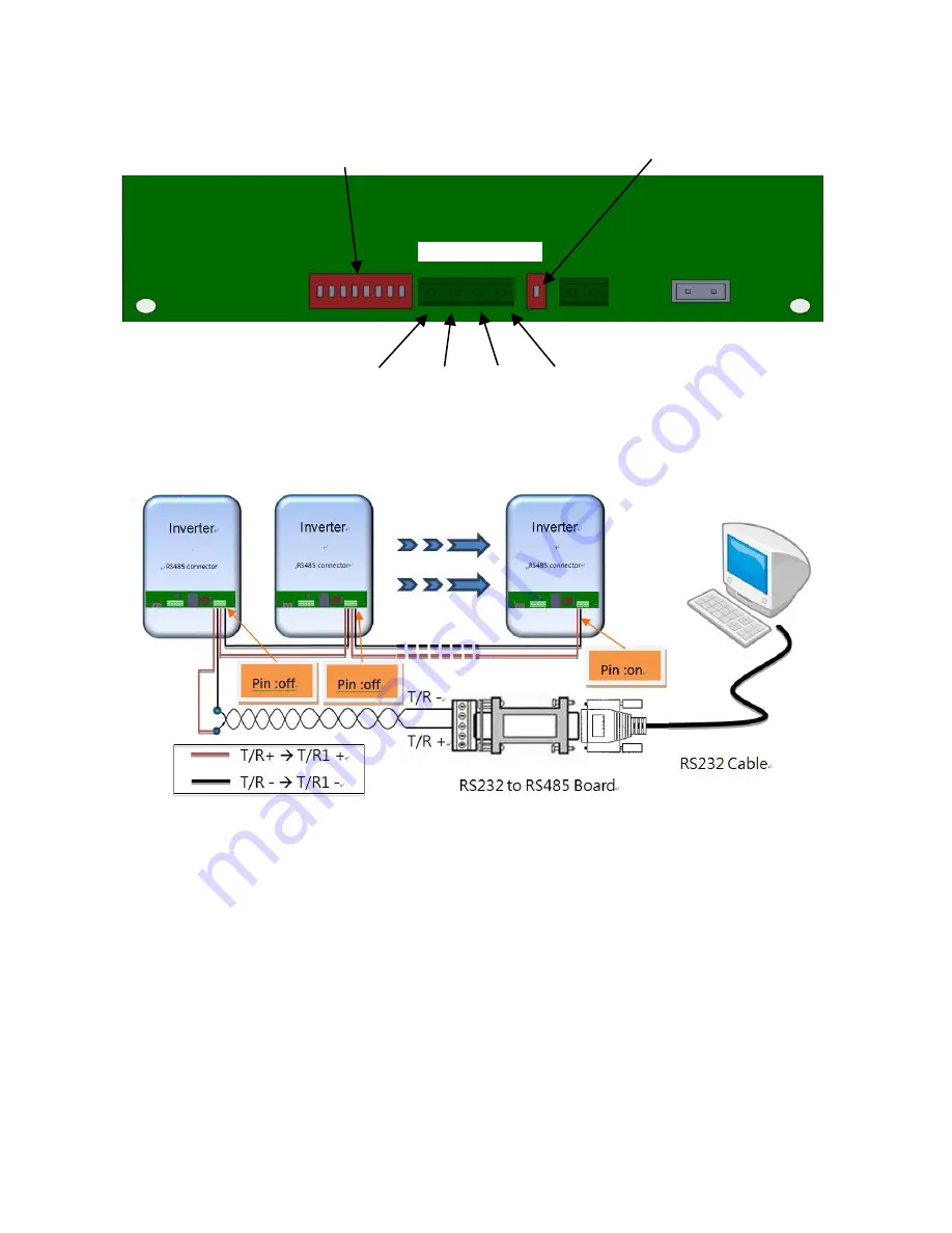
8.2.3 Wiring Diagram
1.
Connect T/R+ and T/R- of RS485 converter to the T/R1+ and T/R1- of
an inverter respectively.
2.
Between two inverters, match T/R2+ and T/R2- of this inverter to
T/R1+ and T/R1- of the next inverter.
3.
Set terminal resistor switch “ON” of the terminal-end inverter (last
inverter of the row) only. The others’ should be set as “OFF.”
8.2.4 Address Setup
To do this setting, use the address rotary switch shown on right. For a single
inverter, set the position to “1”; for multiple inverters, please assign them
different positions with no duplications. Since only 15 positions (1~F) are
available, the maximum number of inverters that can be grouped at a time in a
Address Switch
Terminal Resistor
Switch
RS485 terminal
T/R 1+ T/R 1-
T/R 2+
T/R 2-
Summary of Contents for PV-10000T-U
Page 12: ...11 5 4 Product Labels ...
Page 14: ...13 6 2 Unpacking PV 15000T U ...
Page 15: ...14 6 3 1 Unpacking PV 20000T U ...
Page 16: ...15 6 3 2 Unpacking PV 20000T U E Display ...
Page 17: ...16 6 4 Assembly Chart PV 5000T U PV 8000T U PV 10000T U PV PV15000T U ...
Page 18: ...17 6 5 Assembly Chart PV 20000T U ...
Page 81: ...80 14 Addendum 14 1 Efficiency Charts 14 1 1 PV 5000T U 14 1 2 PV 8000T U ...
Page 82: ...81 14 1 3 PV 10000T U 14 1 4 PV 15000T U ...
Page 83: ...82 14 1 5 PV 20000T U ...
Page 84: ...P N MUB0 A00000 0 ...


