12
COMMISSIONING
STEP 13
INSTALL THE ENTRAPMENT PROTECTION SYSTEM
NOTE: LS-Drive is supplied with a pair of monitored entrapment protection
safety beams. They must be installed for the operator to function.
LS-Drive is not compatible with Grifco GPS15 reflective safety beams or
GLCPS Light Curtain Protector System.
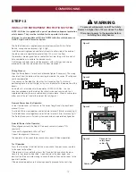
The Safety Beams are supplied preassembled, complete with two Safety
Beams, wiring and wall brackets. (fig1 & fig2)
Install the mounting brackets and Safety Beams to either side of the inside of
the door, and at a height of no greater than 100 mm off the floor.
The brackets are designed to be used for Wall or Floor fixing, with a variety of
hole combinations to achieve the desired results.
Drill the required holes and install the brackets with wall plugs and screws
provided. Ensure they do not obstruct the door movement.
Wiring Process:
Align the Safety Beams to face each other and tighten if necessary. The wiring
should exit from the bottom of the housing to maintain the correct IP rating and
continued operation.
One sensor is a Sending Eye, the other is a Receiving Eye. Try to avoid
positioning these in direct sunlight as this may interfere with the operation of the
beams.
Run both sets of wire back to the operator CONTROL PANEL. Use the
channels provided on either side of the rail extrusion and secure with the 4
supplied cable clips to ensure cable does not come loose. Mount a cable clip at
either end of the rail - and either side of the rail (figure 4)
Remove Power from the Operator:
At the Operator end, cut the wires to the correct length and strip each back
around 10 mm.
Twist both White wires together and install into terminal 2 (White terminal) (fig 3)
Twist both Black wires together and install into terminal 3 (Grey terminal) (fig 3)
The Safety Beams are a 2 wired system connected in a parallel configuration.
Reinstall Power to the Operator:
When aligned correctly the Red LED on each sensor will remain “ON
constantly”.
If incorrectly aligned both LEDs will “flash”.
Correct the alignment if necessary.
The operator is now ready to be checked for correct IR Beam operation.
Test Operation
Press the Up button in the Control Panel and check the door travels smoothly
to the open limit position.
If there are no issues detected, press the Down button and check the door
travels to the closed limit position. Open and close the door again, and
obstruct the IR beam while closing to check the door stops and reverses to the
open limit position.
If the door and operator are functioning correctly proceed to the next step.
Figure 1
Figure 2
Figure 3
Figure 4
Channels for
safety beam
cables
Cable clip
To prevent entrapment, install The Safety
Beams no higher than 100 mm above the floor.
Disconnect power to the operator before
installing the safety beams.
WARNING
White x 2
Black x 2


