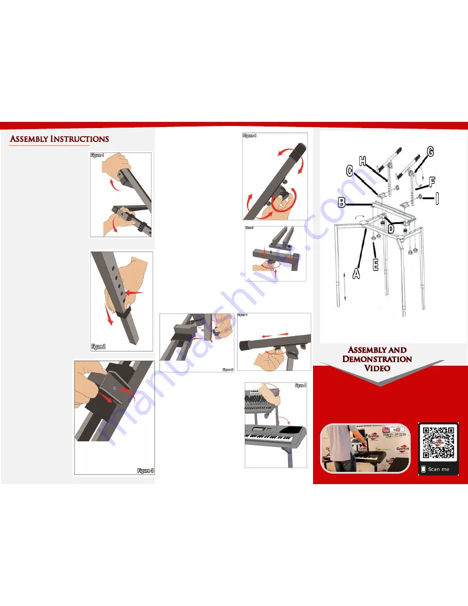
Step 4
–
Locate 2 pairs of
plates (Part D), take 1 and
place the plate with a screw
knob (Part E) on the bottom
of the crossbar and the other
one on the top parallel to the
plate at the bottom. Screw
the knob at the bottom to
secure the plates together as
shown on
Figure 4
.
Step 7
–
For safety reasons,
please always make sure to
test the stability and safety of
the
product
before
use.
Double check all nuts and
bolts, knobs and connectors,
make sure that these are tight
and securely fastened before
use of your product. Test the
product under light use or
light loads the first time to
confirm
assembly
and
structure of the product is
correct.
Step 1
–
Locate the leg
assembly (Part A) and as seen
on
Figure 1
expand and
unfold the legs of the stand.
The front legs can be spread
apart as far as needed. The
distance between the back
legs is determined by the back
crossbar.
Step 2
–
To adjust the height
of the stand, each bottom of
the legs has a silver push pin
that is pushed to allow the
slots of the legs to adjust.
Pushing or pulling the bottom
part
will
be
the
height
adjustment, if the pin is on
the 3rd hole of one leg make
sure that all the other pins are
on the 3rd hole as well on the
other legs. Refer to
Figure 2
.
Step 5
–
Take the arm (Part F
and H)and line the bottom
with the mount on the plates
you installed on Step 4. See
Figure 5
. Tighten the knob to
secure the arm in place.
Step 6
–
Figure 6
shows the knob (Part G) on the side of
the arm to adjust the angle and
Figure 7
shows a knob
just below the arm to slide it front and back.
Please scan the QR Code below for the product
demonstration video. Or go to the URL shown here and find
the product video. www.Griffin-Stands.com/Videos
Step 3
–
Place the
crossbar
(Part
B)
across
the
leg
assembly and line up
the nuts welded to
the crossbar with the
two holes closest to
the front of the stand
on each side (See
Figure 3
)


